In general, a voltage doubler (the second circuit) will be inferior to a full wave rectifier,
having poorer regulation. Also both halves of the doubler should be equally loaded, and
have at least twice the capacitance of the full wave circuit, because it is only half wave.
having poorer regulation. Also both halves of the doubler should be equally loaded, and
have at least twice the capacitance of the full wave circuit, because it is only half wave.
Last edited:
If a single rail supply amplifier is "working well " the only reason I can see that you want a split rail is to allow a larger signal output without clipping---Rayma is right by the way .
What is your point, are you going to build another amplifier or modify the single supply one which--as you say--is working well -- ?
Why do you want a 10 amp supply are you going to blast your neighbours or are your speakers very inefficient ?
The heavier the supply the more a design configuration has to be taken into account as to heat /wattage of components /heatsink etc.
I want to build a new amplifier. I already have a 35+35 vac
10A transformer. I want to use it as 0-70vac. My circut operates on 70+70 vac. What you say about it
10A transformer. I want to use it as 0-70vac. My circut operates on 70+70 vac. What you say about it
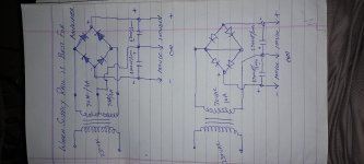
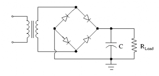
If you require 0/70 and have a 35/0/35, then the best way is a FWB,
with the windings in series, and one capacitor. Don't use the common center connection.
If you don't have capacitors of adequate voltage rating, then series connect two
electrolytic capacitors, with a parallel 10k resistor for each to balance the voltage division.
with the windings in series, and one capacitor. Don't use the common center connection.
If you don't have capacitors of adequate voltage rating, then series connect two
electrolytic capacitors, with a parallel 10k resistor for each to balance the voltage division.
Attachments
Last edited:
Please under stand my question.
My amp requierment 70-0-70. I have 35-0-35. If i use 1st loop as commom and last loop as 70v. And connect 70v to bridge rectfier both Ac. The out put will +&- 70v. Now can i use this in amplifier
My amp requierment 70-0-70. I have 35-0-35. If i use 1st loop as commom and last loop as 70v. And connect 70v to bridge rectfier both Ac. The out put will +&- 70v. Now can i use this in amplifier
If you need +70VDC/0/-70VDC, there is no simple way to get that from dual 35VAC windings.
Normally you would use series connected dual 50VAC windings and a full wave bridge for that.
Or do you mean that you actually need +35VDC/0/-35VDC instead?
Normally you would use series connected dual 50VAC windings and a full wave bridge for that.
Or do you mean that you actually need +35VDC/0/-35VDC instead?
Last edited:
This looks to me, a call to using a bridged output stage ( aka H drive ). One legs swings +35 /0/ -35 while the other leg swings in opposite phase -35/0/+35. So the loud speaker can get near 70v peak.Please under stand my question.
My amp requierment 70-0-70. I have 35-0-35. If i use 1st loop as commom and last loop as 70v. And connect 70v to bridge rectfier both Ac. The out put will +&- 70v. Now can i use this in amplifier
- Home
- Amplifiers
- Power Supplies
- Which supply rail is best for Amplifier