Well, the improvement in damping factor (perceived as better low-end extension and control), and much better high-end extension (as measured) - all with that loop closed, in your case yields more enjoyable listening pleasure - which is all that matters.
I completely agree with you - those old analog master transfers sound so good. JJ Cale Gold (2CDs collection) is one of my favourites.
I completely agree with you - those old analog master transfers sound so good. JJ Cale Gold (2CDs collection) is one of my favourites.

I followed a different approach and did not put any capacitor in the feedback path. I used open loop frequence response tayloring in the phase splitter by placing a capacitor between the anodes (V2 in your diagram). You can play with the capacitor values, or even use a serial R-C. I first simulated it in LTSpice, then refined it in the actual circuit. Do it at low power.
Interesting approach. I have LTSpice loaded and have played with simple circuits but am not familiar enough to put an amp circuit in yet.I followed a different approach and did not put any capacitor in the feedback path. I used open loop frequence response tayloring in the phase splitter by placing a capacitor between the anodes (V2 in your diagram). You can play with the capacitor values, or even use a serial R-C. I first simulated it in LTSpice, then refined it in the actual circuit. Do it at low power.
Did you notice a change in the square wave shape, after you installed the R/C, between open and closed loop or did it remain the same. It's very simple for me to try while the amp is still apart.
Thanks
Sitting here rethinking my approach to this and am wondering if I should try cleaning up the ringing at the source, rather than fixing it with feedback? I am almost certain that the ringing is the output xfmr and in open loop testing the stages from input to output will reveal that the square wave is clean until it gets to the transformer. Perhaps a different approach to control the ringing is called for, i.e. clean it up at the source, damping resistors or small R/Cs around the transformer, then apply feedback without any or minimal C.
Something to play with.
Cheers
Something to play with.
Cheers
I think you're overthinking it. ;-) That is NOT a lot of ringing, the feedback is doing it's job, the top of the waveform is dead flat, so no oscillation in sight. Have you tried it with some capacitance across the fixed load? Try .1uF. If it doesn't disrupt the square wave much, the amp is very stable.
Last edited:
Thank you for your thoughts, much appreciated.
Now that I am thru my ordeal with the power transformer, which was an issue caused by myself, I can now continue on my journey of tuning this amp. I found an excellent article in Glass Audio #3-'95 about tuning ringing in output xfmrs, the article is called "The snubber". I have seen a similar approach here T-E SMITH feedback tuning.
To be continued...
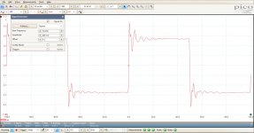
FYI, here's some ringing for you. ;-) That's an untamed Acro TO-330 in a stock Williamson circuit.

Is that the waveform at the output of that transformer?? If YES, that's a fast response capability... for a transformer... nice.
Is that the waveform at the output of that transformer?? If YES, that's a fast response capability... for a transformer... nice.
I was thinking exactly the same thing, so easy to tune that one.
I would like to know why my amp/xfmr seems to be so slow, rise/fall is terrible compared to the ACRO TO-330. Is it the xfmr, circuit or ?? I'm pretty sure it's the xfmr.
Cheers
PS Here is a link to a fine piece of work by Norman Crowhurst, Audio Handbook #2, Feedback Feedback by N. Crowhurst I just started reading it, from 1952 but just as relevant today.
Last edited:
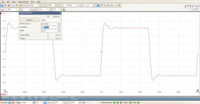
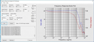
You don't want that waveform. That amp will oscillate if you breathe on it. ;-) It's partly the Acro and partly the feedback, but mostly the Acro. Amazing bandwidth but they're tough to tame. I can't find the Bode plot I did for that, but it's got ultrasonic peaks all over the place and multiple phase shifts. Below are pix of a Heyboer copy of the Peerless S-265-Q at 10kHz, almost exactly the same circuit, plus the Bode plot I ran. The difference is that this time it's stable even with some capacitance across the load. And there's no lack of HF response. There's a bit too much overshoot which I tamed with a slightly larger phase-lead cap, but you get the idea. You really don't want straight sides at 10kHz.
Attachments
Last edited:
GG, what version of Pico scope are you using? I think you have me on my way to some new test gear, that is very cool. I had a quick look on the web and see them from $165 to $15,000.
Thanks
Thanks
I use the 2204A, which was about $350. It's fine for DIY amps and such. The built-in signal generator goes up to 1mHz, which lets you check the supersonic response of a feedback amp. There's a third-party app for Windows you can find on the Picoscope site that can run a Bode plot and check for phase shifts, phase margin etc. Very handy.
Here's the app:
https://www.picotech.com/library/picoapp/frequency-response-analyzer-with-bode-plots
The only downside of the Picoscope is that the signal generator only puts out up to 2 volts. For testing for clipping, etc., I have a separate digital generator with higher output. But for the Bode plot app you need to use the Picoscope's internal generator. For testing at 1-20 watts output or so it's fine, depending on your amp's sensitivity, of course.
I checked their site and the 2204A is $165 and without probes $129, am I missing something? Are the included probes worth it or will my classic Tektronix probes work, of which I have many?I use the 2204A, which was about $350.
Thank you.
- Home
- Amplifiers
- Tubes / Valves
- Which square wave do you think is best...tuning an amplifier