Hi all.
I'm going to make the LM1875 and have found two layouts which look nice and compact (and more importantly, for me anyway, have PCB images).
I'm interested to see which one would be the most popular choice amongst the more experienced members of the forum. Personally I like PCB-2, but only for its simplicity and lower number of components. Or maybe somebody could offer a better alternative?
Your feedback would be invaluable to a newbie like myself!
Thanks a mil!
John
Attachments

Last edited:
I vote for PCB-3.
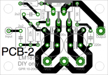
PCB-2 has one big disadvantage. The capacitor on the inverting leg is too small. While the roll-off may be okay for a guitar amp, it is far too high for hi-fi and it is 22 times higher than at the non-inverting input when it should be lower or equal. Pity that there is not enough space to use a bigger capacitor there.
PCB-2 has one big disadvantage. The capacitor on the inverting leg is too small. While the roll-off may be okay for a guitar amp, it is far too high for hi-fi and it is 22 times higher than at the non-inverting input when it should be lower or equal. Pity that there is not enough space to use a bigger capacitor there.
The layout of PCB 2 was designed by me about one year ago as tweeter amplifier but it had some flaws. Speaker ground is not on the board, it has to be taken from the power supply. I could not get rid of the hum until i did that. Although are a lot of other PCB versions for LM1875 on this forum, here's another one.
Attachments
PCB 1 gets my vote (PCB 2 has poor decoupling/grounding). Notice how the return currents through the decouplers have their own path back to the ground pin - not shared with any signal paths.
PCB1 nearly gets my vote.
I spotted it a few days ago but did not comment.
The speaker return only works for a monoblock amplifier.
As soon as you go to two or more channels the Speaker Return must be moved off board to the Main Audio Star Ground, that is shared between all channels.
The 100nF at the +ve power pin can be rotated through 90degrees to shorten the route for the decoupled currents. 0.1inch pitch caps here should perform even better since they will allow a shorter current route. Remember to correct the labels at the power input spades.
The Signal Ground should have an option for a direct connection to Power Ground or a resistor connection to Power Ground.
There is plenty of space to add that extra resistor option.
The extra resistor should have a pair of inverse parallel diodes in parallel to limit the voltage between Safety Ground and Signal Ground in the rare event of a Fault Current passing.
Saw that, but I need a clean PCB layout without all the components drawn on it...😀
*enjoying Big Bang Theory Series 3 marathon :O)*
Evening all!
Thanks to you all for your votes, comments and ideas. Interesting that it's level pegging, and cheers to Ratza for his contribution to no. 3 which looks like a nice layout.
After some consideration and a couple of beers, I've decided to try both 1 & 3, and possibly implementing some of the alterations that AndrewT suggested. I've been planning to buy some protoboard so my little boy can try out some circuits and it could be quite interesting - maybe I will discover the perfect layout (does it exist?)
Will post the results as and when!
Cheers as always!!
John
- Status
- Not open for further replies.
- Home
- Amplifiers
- Chip Amps
- Which LM1875 layout would you choose?