I'm working on a two way xover design. When using the basic crossover formulas, I see from most readings to use the nominal driver impedance.
However, I have also read that one should use the drivers impedance at the crossover point.
In my case the driver is nominal 8 ohm. However, at 2K, my choice of xover point, the impedance is 15 ohms. Which do I use in the formula 8 or 15?
However, I have also read that one should use the drivers impedance at the crossover point.
In my case the driver is nominal 8 ohm. However, at 2K, my choice of xover point, the impedance is 15 ohms. Which do I use in the formula 8 or 15?
None of the above. Drivers have wildly varying impedance versus frequency, not to mention frequency response. The percentage of by-the-book crossovers that actually work approaches zero. What you need to do is get some basic speaker CAD software (cheap), get the impedance and frequency response curves of the drivers you have in mind, put them into the program, then start playing. The first one that pops out will likely not be optimum when you actually solder it up and attach it to your drivers, so you'll find it to be an iterative process.
Dickason's Loudspeaker Design Cookbook would be a VERY worthwhile investment.
Dickason's Loudspeaker Design Cookbook would be a VERY worthwhile investment.
LDCB has the same formulas I'm using in order to calculate the values of the components of a 1st or 2nd order xover. The formulas don't employ an entire curve. You have to pick a frequency and an impedance when using the formulas.
which is it? nominal or the value at the xover freq. after acquiring the impedance plot? If it's neither, then what do I use?
which is it? nominal or the value at the xover freq. after acquiring the impedance plot? If it's neither, then what do I use?
What SY said.
Unless you only plan to have the driver play one frequency, you will really want to pull the impedance curve from the datasheet & compute the crossover effects throughout the audio band. I did this with a free digitizing program called Engauge, and some custom VB coding to get evenly spaced SPL & impedance points. Then I tossed it all into excel & used formulas to compute passive XO values.
There is probably also freeware out there that can do it for you. I sissied out & went active...a little more $ up-front, but it seems to be easier to me in the end, and there are technical benefits (much greater driver damping, no risks if you run the amp with no load, way easier to calculate, etc). Anyway, if someone here suggests good passive XO software, I'd be interested to give it a try. Passives take a little more work up-front to do right, but they can be very good when done right.
Originally posted by skeptic43
In my case the driver is nominal 8 ohm. However, at 2K, my choice of xover point, the impedance is 15 ohms. Which do I use in the formula 8 or 15?
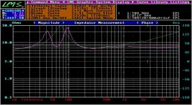
Apply a suitable zobel network to convert the driver's impedance to resistive. Now, with a fixed resistive value over the frequency range, your passive crossover will conform to your calculations. Below is a plot of a woofer in free air and one loaded in a vented box with a zobel network applied.
To check the behaviour of your crossover with your driver connected, you need a program that you can do a Transfer Function. This will show you the electrical behaviour of your passive network togather with your driver.
For acoustic summation, a Gated SPL sweep of individual drivers with their respective crossovers is done followed by a final sweep with LF and HF connected.
With these plots, you will be able to see the interaction of the passive networks electrically and acoustically.
Mike
Attachments
- Status
- This old topic is closed. If you want to reopen this topic, contact a moderator using the "Report Post" button.