I'd like to make a stereo pair of the hybrid cascode input stage described in MerlinB's "Building High Fidelity Tube Preamps" using a 12AU7 and an LSK389 (matched pair of LSK170 jFETs on a single 6-legged device).
I have no experience with 2SK170, LSK170, etc., and I notice that there are three grades, A, B and C, rated for different Idss. For this application, which grade do I want?
Also, I ran some simulations in LTspice, using a couple of different models for LSK170 and 2SK170. In all cases I get the best results (easiest biasing, lowest predicted THD) using the C grade, which is the one that draws the most current (highest Idss, I think). Strangely, these are slightly cheaper than the A and B grades. Is there a downside to using the C graded part? Any reason to specify an A or B grade? They're expensive, so I'd rather avoid buying multiples to try and see.
Thanks.
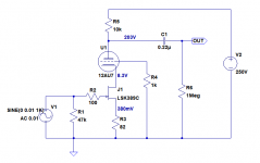
Absolutely. Here's the hybrid cascode input stage with the LSK389 as the bottom half of the cascode (attached .asc file).
I think I'm using the model from the Linear Systems website. Substitute LSK389A and then LSK389B to see how it changes things.
I used the Ayumi 12AU7 model from the LTspice tube models thread in this forum.
I think I'm using the model from the Linear Systems website. Substitute LSK389A and then LSK389B to see how it changes things.
I used the Ayumi 12AU7 model from the LTspice tube models thread in this forum.
Attachments
Is there a downside to using the C graded part?
Not that I can think of. You'll still have the usual manufacturing spread in Vgs(off) so the source resistor will always need tweaking to set the idle current, whatever grade you buy. It's six of one and half a dozen of the other!
Slight diverge in the subject, but I am using a 2sk369b in a cascode phono stage. However I would like a little more gain. Can I parallel 4 c grade lsk170 to 1 . Get more gain using the C grade. And 2 run more quietly by using 4 jfets?
the 380mV and 82r tells us that the jFET is passing 4.63mAAbsolutely. Here's the hybrid cascode input stage with the LSK389 as the bottom half of the cascode (attached .asc file).
I think I'm using the model from the Linear Systems website. Substitute LSK389A and then LSK389B to see how it changes things.
I used the Ayumi 12AU7 model from the LTspice tube models thread in this forum.
Any k170 jFET with an Idss >5mA can be set up to pass 4.63mA by adjusting the 82r.
You could use a B grade and a lower value R3 or maybe a high end A grade. If you selected an A grade with an Idss = 4.63mA, then R3 value becomes zero ohms.
If you look at the datasheets you will see that all grades have virtually identical gm at the lower currents. This leads us to the conclusion that if you operate at a lower current then there is no advantage in selecting a high Idss device.
A consequence of using a lower Idss device is lower Vgs at your selected Id.
A consequence of using a lower Idss device is lower Vgs at your selected Id.
Thanks for your detailed reply (and to Merlin for his too).
What if any consequence is there to operating the JFET in the example circuit with a low Vgs? I expect the highest input level it would see will be about 90mV peak.
In these JFETs, is there 'gate current' as Vgs gets close to zero?
I'm hoping that choosing the LSK389 two-matched-on-one-die version will save me some trouble getting stereo pairs. The example circuit is meant to be the input stage for a MM RIAA preamp.
Looking at the simulation's directive (.trans), why would it show using the 'C' grade yielding half the harmonic distortion compared to using the 'B' grade JFET? Is that just a simulation artifact that's not indicative of what to expect in real life? Or might LTspice be on to something?
--
I've attached an example schematic
--
Attachments
Last edited:
I'm not a spice user but I'll guess the change in distortion predicted by your simulation is because you have asked the wrong question for the data you put in.
As to low Vgs, the Pass B1 and Salas DCB1 both operate with virtually zero Vgs.
There is a body of opinion that jFETs may perform a bit better when Vgs becomes negative, but don't go too far. Id ~ 50% to 90% of Idss seems to be a good operating window. Don't be afraid of using 99% of Idss, if you can keep them cool.
Thank you Merlin, may I ask you a detail on the hybrid cascode shown at page 308 of your book?Not that I can think of. You'll still have the usual manufacturing spread in Vgs(off) so the source resistor will always need tweaking to set the idle current, whatever grade you buy. It's six of one and half a dozen of the other!
I actually have bought a pair of monoblocks with a similar configuration for the Schmitt phase inverter (LSK170 on the bottom, 12AT7 on the top, with grid voltage set by a voltage divider at around 13V), biased with a CCS at 1 mA per side and with 220 kOhm load for the upper triode.
It needs to swing around 80Vpp (a pair of EL34 in PP with B+450V, 7 kOhm Raa and UL43%) with classical 2Vrms at its input. I've got feedback that it is not its optimal application, but results are not bad. Is there any improvement you would suggest for this application?
Thank you in advance.
- Home
- Amplifiers
- Tubes / Valves
- Which grade LSK389 to use for hybrid cascode a la Merlin B.