I'm looking for equivalent diodes for 1N4003's used in a power supply, but having difficulty identifying which specs are relevant and which are not. For example the
1N4003 gives: Vpeakrev=200, Vrevrms=140, CurAve=1.0A, CurPeak=30, FwdVolt=1.0V.
Schottky11DQ09 gives: Vpeakrev=90, Vrevrms=?, CurAve=1.0A, CurPeak=30, FwdVoltDrop=0.68-0.96V.
Some Hexfreds give a FwdVoltage drop of 2.2V and CurAve=25A others 15A.
I'm not sure which measures are relevant to my application and which are not. (I'm not designing a circuit, just trying to consider what would be good equivalent replacements.)
You can reference my power supply schematic if that helps (attached).
Attachments
I'm looking for equivalent diodes for 1N4003's used in a power supply, but having difficulty identifying which specs are relevant and which are not. For example the
1N4003 gives: Vpeakrev=200, Vrevrms=140, CurAve=1.0A, CurPeak=30, FwdVolt=1.0V.
Schottky11DQ09 gives: Vpeakrev=90, Vrevrms=?, CurAve=1.0A, CurPeak=30, FwdVoltDrop=0.68-0.96V.
Some Hexfreds give a FwdVoltage drop of 2.2V and CurAve=25A others 15A.
I'm not sure which measures are relevant to my application and which are not. (I'm not designing a circuit, just trying to consider what would be good equivalent replacements.)
You can reference my power supply schematic if that helps (attached).
I've used these:
VISHAY BYV26C-TAP http://www.farnell.com/datasheets/57068.pdf
Look to the application, rather than the data-sheet - with caveats! 😀
When I managed a design team very many years ago I tried to minimize inventory by standardizing parts.
AFAIR, the purchase cost difference between a 1000V 1N4007 and a 100V 1N4001 was absolutely tiny. They are the same part, just selected on test.
So I insisted on 1N4007 only be stocked and used, even for the lowest voltage application.
One day, of course, an inquisitive engineer might ponder why there are 1kV diodes in this 5V PSU! And then insist on a 1Kv replacement part, just to be safe ...
lots of YMMV here .. depends on the market and quantities.
Yes... so I have a relatively simple preamp power supply 245vac input to the diodes then through a 1000uF 35V cap into 15V voltage regs (LM2940/LM2990) and then through another 1000uF 35V cap. How do I know what the Vr (peakrev) should be? And should 15A Ifsm be well sufficient, or what specs do I need to be careful of?
I think you've erred describing your power supply. "245vac input to the diodes" leaves out the voltage stepdown transformer, doesn't it? I sure hope so...
Anyhow, assuming a bridge rectifier, consider the voltage peak that the capacitor will charge to. Then consider the opposite polarity ac signal on the other side of the diode - that is your Vr (peakrev). For example, if the cap charges to +20v and the ac signal is at the -20v point of the waveform, there will be 40v of reverse bias across the diode.
Diodes have a continuous current rating and a surge current rating. For the 1N400x series I think it's about 1A continuous and 40A surge. Rectifier current is more surge than continuous. For a preamp you probably can't go wrong with any rectifier diode, i.e., just stay away from signal diodes.
Keep in mind the qualifiers used for these examples. Half-wave and center-tapped full-wave rectifiers, used with C or L filtering, may be different.
Also, 0.7v @ 1A implies a power rating of just 700mW. So even though a diode's surge rating in amperes may be much greater than 1A, in practice it's the average power dissipation that is the determining factor.
Also, 0.7v @ 1A implies a power rating of just 700mW. So even though a diode's surge rating in amperes may be much greater than 1A, in practice it's the average power dissipation that is the determining factor.
Brucew268, the schematic you posted requires a diode with these characteristics
Farnell-UK lists many of these diodes on their website, and Maplin-UK lists a couple of them.
- Package = DO-41 (aka DO-204AL) ... assuming you want to solder into the original PCB
- Reverse voltage greater than 120 volts
- Forward voltage @ 1ampere, less than 1.1 volts
- Continuous forward current > 1.0 amperes
- STPS1150
- MUR120
- EGP10D
- FGP10D
- UG1D
- STTH102
- 1N4003, 1N4004, 1N4005, 1N4006, 1N4007
- UF4003, UF4004, UF4007
- 1N3611
- STTH1R02
Farnell-UK lists many of these diodes on their website, and Maplin-UK lists a couple of them.
I expect to solder into the pcb with through holes at about 10-11mm. Thank you for this info. Will do a bit of looking about this week. Why is the 120 reverse voltage and the guitars voltage drop of less than 1.1v? I see that many of the ultrafast have a forward drop off around 2.
Perhaps your mobile device performed "auto-correct", the word guitar was a bit unexpected -- ??
Your existing PCB may, or may not, have drill-holes large enough to accommodate the leads of other diodes in non-DO-41 packages. For example, the wonderful 1N5404 diode (DO-201 package, 3 amps rating) has 0.051" diameter leads. Its leads would not fit in holes drilled for an 1N4003 (DO-41 package, 0.034" diameter leads). On the other hand, perhaps your PCB is drilled with truly gargantuan hole sizes, perhaps 0.063". If that were true then you could use 6 amp or even 10 amp axial lead diodes and obtain enormous safety margins.
The DO-41, having been used before, can safely be assumed to fit. Anything larger amounts to making a bet; a bet that you could lose.
If you're going to fit into the existing unmodified PCB, you need to consider lead spacing, lead diameter, and (possibly) body diameter .... if there is another component or chassis member immediately above the diode's mounting position.
Last edited:
LOL! Guitar = forward. I was curious about the basis for 'Forward voltage drop' and 'Reverse voltage'
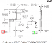
Lots of good help here. Thank you. BTW: HexFred does seem to be a possible option for an existing PCB using the TO-247 package. The lead spacing is about 11mm and lead width is said to be 0.99mm. (The diode holes on my PCB are 1.0mm, 11mm apart.)
For example Vishay's HFA15PB60PBF or HFA25PB60PBF.
...or I may just stick with the Schottky 11DQ10's.
For example Vishay's HFA15PB60PBF or HFA25PB60PBF.
...or I may just stick with the Schottky 11DQ10's.
Oh well, you risk £12 and sometimes you lose. I ordered the HexFred HFA15PB60PBF and found that the lead is 1.21mm x 0.69mm, larger than indicated in the datasheet, and won't fit in my 1.0mm holes. No big deal I guess; I'll stick with my Schottky.
I took a look at the datasheet and found this drawing on page 6.
It appears to say that the lead width (which I will call "W") and the lead thickness (which I will call "T") are permitted to fall anywhere in the min/max range:
Good old Pythagoras tells us that the required hole diameter is sqrt(W^2 + T^2) = 1.612 mm, after plating.
_
It appears to say that the lead width (which I will call "W") and the lead thickness (which I will call "T") are permitted to fall anywhere in the min/max range:
- 1.00 mm < W < 1.40 mm {red}
- 0.40 mm < T < 0.80 mm {green}
Good old Pythagoras tells us that the required hole diameter is sqrt(W^2 + T^2) = 1.612 mm, after plating.
_
Attachments
Last edited:
I got all of the engineers at work last week with this question:
which has the highest current rating: 1N5408 (3A) or STTH16L06 (20A or so).
the obvious answer (STTH) of course is exactly wrong if you look at i_FSM - the single half-cycle surge current rating. the huge dual fast diode has i_FSM = 120A whereas the 1N5408 has i_FSM = 200A.
sure one is spec'd at 50H the other 60Hz but a quick bit of maths shows that aint even close to the difference. especially when one considers the continuous current rating.
THIS is why a 1N5408 is so often spec'd as a boost converter bypass diode in boost PFC circuits. i havent looked in a while, but istr SiC schottkies are even crappier wrt i_FSM
and boy was this hard to explain to folks with ESL. even with the two datasheeets, many folks didnt believe me.
apparently all that super fast stuff comes at a cost....
TANSTAAFL
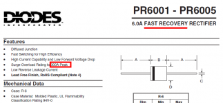
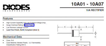
Diodes Inc. provides a nice table that shows the current "surge" (I_FSM) ratings for several different diode types:

Their website also lets you sort by I_FSM. This revealed a fairly low-cost "fast" diode rated for 300 amps surge: the PR6004:

The sort feature also turned up the 10A04, which is a standard slow diode like the 1N5404, but rated for 600 amps surge:

Their website also lets you sort by I_FSM. This revealed a fairly low-cost "fast" diode rated for 300 amps surge: the PR6004:
The sort feature also turned up the 10A04, which is a standard slow diode like the 1N5404, but rated for 600 amps surge:
Attachments
Last edited:
I'm looking for equivalent diodes for 1N4003's used in a power supply, but having difficulty identifying which specs are relevant and which are not. For example the
1N4003 gives: Vpeakrev=200, Vrevrms=140, CurAve=1.0A, CurPeak=30, FwdVolt=1.0V.
Schottky11DQ09 gives: Vpeakrev=90, Vrevrms=?, CurAve=1.0A, CurPeak=30, FwdVoltDrop=0.68-0.96V.
Some Hexfreds give a FwdVoltage drop of 2.2V and CurAve=25A others 15A.
I'm not sure which measures are relevant to my application and which are not. (I'm not designing a circuit, just trying to consider what would be good equivalent replacements.)
You can reference my power supply schematic if that helps (attached).
I would tend to stick with 1N4003, as the 78X 79x are not going to be any better, although they work, they are miserable for audio related circuits.
A really imaginative circuit would see the LT4320 with some N channel Hexfets and followed by mosfet cascode regulators.
Last edited:
- Status
- Not open for further replies.
- Home
- Amplifiers
- Power Supplies
- Which diode specifications for equivalence?