I also mention to a bit off the record.
The feedback resistance from the collector to the base determines the gain along with the impedance of the MC cart, and should also play a role in determining the collector voltage of Q1 and Q6. In the circuit shown above, the DC servo operates so that the base voltage is 0V, but I think either Q1 or Q6 will be saturated and will not operate normally.
I think it is necessary to ground the collector through about 100R or make U1 a transimpedance configuration (an I/V conversion circuit).
Of course, Q1 and Q6 operate without feedback, but this is unavoidable.
Hi Mason,
I do not get what you mean.
It’s not the collector who drives the feedback resistor back to the bases, but the LT6203’s output does the job.
There is no collector saturating, all the collectors have to do is to drive the opamp’s high Zin input.
And the servo is responsible for setting the input to zero volt.
The circuit is already working flawlessly for several years and can be used as a voltage amplifier or as a transimpedance amp.
Hans
Re post 20 : why don't you use any input and collector load and how do you define gain here ?
Thanks.
Thanks.
Hi Hans. Sorry for taking up your time. I finally understand. I was thinking of the same circuit as #20.

Apparently, as_audio was thinking the same way as me.
Apparently, as_audio was thinking the same way as me.
Just regard the shown circuit diagram as an op-amp with a positive and a negative input.

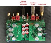
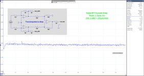
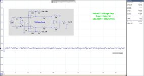
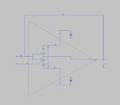
I used this in a differential head amp, as voltage amp and as transimpedance amp, here as an example with a low output 1R Cart and 50X gain.

The op-amps at the left are the above circuits, and the third op-amp at the right is a LT6234.
Hans
I used this in a differential head amp, as voltage amp and as transimpedance amp, here as an example with a low output 1R Cart and 50X gain.
The op-amps at the left are the above circuits, and the third op-amp at the right is a LT6234.
Hans
So perhaps you should add that the circuit in post 20 (and 15 also) is not a working pre-pre,
but a simulation exercise, at least not due to the missing input bias path.
It is a completely different task to build a head amp using two transistors or three op-amps.
This thread is about a discrete head amp I thought.
but a simulation exercise, at least not due to the missing input bias path.
It is a completely different task to build a head amp using two transistors or three op-amps.
This thread is about a discrete head amp I thought.

You misinterpreted the two op-amps at the left.So perhaps you should add that the circuit in post 20 (and 15 also) is not a working pre-pre,
but a simulation exercise, at least not due to the missing input bias path.
It is a completely different task to build a head amp using two transistors or three op-amps.
This thread is about a discrete head amp I thought.
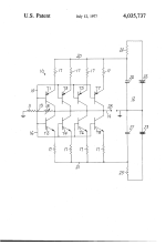
They are as discrete as discrete can be based on the John Curl patent.
These are the circuits as shown in #25.
And there is no missing bias, sorry.
Hans
This thread is essentially about two transistor head amps, Mark Levinson John Curl JC1 xx .
Of course you can define your op amp triangles as being set up in a discrete way, but this is
not the point.
Your post 15 schematic is not complete, and so the statement "The circuit below is also a JC
design" can not be true.
The same applies to post 20, not complete without input resistor etc - but if it is only part of
a later revelation (post 25) you should mention this.
I expect the same precision here as we are used from your earlier contributions.
as_audio, Thx for having high expectations.
But since this is not your thread, let the O.P. be the judge of that.
Sorry Tiefbass to intrude your thread once more, but as I mentioned before, it was a bit off topic, but could be interesting for those wanting to modernize their JC-1 with components that were not available at the time JC applied his patent, while still keeping as close as possible to the essentials.
@as_audio, with all your remarks it seems you are having a problem in reading electronic circuits.
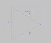
So let me start telling that a triangle is the universal defined way to display an amp.
Telling that that is incomplete, is telling that every op-amp is incomplete.
So starting with the first attachment, this is most rudimentary version of the JC-1.
Second attachment is the Triangle filled with JC's patent.
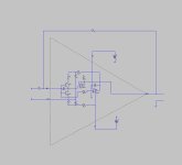
Third one is the version with two modern low noise transistors.
The fourth one is the version with a buffer to improve characteristics plus a servo to keep input at zero volt.
Hans
But since this is not your thread, let the O.P. be the judge of that.
Sorry Tiefbass to intrude your thread once more, but as I mentioned before, it was a bit off topic, but could be interesting for those wanting to modernize their JC-1 with components that were not available at the time JC applied his patent, while still keeping as close as possible to the essentials.
@as_audio, with all your remarks it seems you are having a problem in reading electronic circuits.
So let me start telling that a triangle is the universal defined way to display an amp.
Telling that that is incomplete, is telling that every op-amp is incomplete.
So starting with the first attachment, this is most rudimentary version of the JC-1.
Second attachment is the Triangle filled with JC's patent.
Third one is the version with two modern low noise transistors.
The fourth one is the version with a buffer to improve characteristics plus a servo to keep input at zero volt.
Hans
Attachments

Sorry, if you read I wrote that your schematics 15 and 20 are not complete - and I see no "triangle" there.
Now, in a new post 30 you added the necessary components that we did not know of earlier and this is what I asked for ..
Now, in a new post 30 you added the necessary components that we did not know of earlier and this is what I asked for ..
after update this forum here the currently URLs:some info in the wrong thread (hard to find without navigation hints/post numbers):
http://www.diyaudio.com/forums/analog-line-level/146693-john-curls-blowtorch-preamplifier-part-ii-1934.html (post #19332 and #19334)
http://www.diyaudio.com/forums/anal...urls-blowtorch-preamplifier-part-ii-4370.html (#43694)
My schematics of JC1-DC are to find on many websites over the world - e. g.
Mark Levinson JC-1DC
BTW - here a rebuild module based of the JC-2
Mark Levinson 1 - cbznob???? - Yahoo!???
https://www.diyaudio.com/community/threads/john-curls-blowtorch-preamplifier-part-ii.146693/page-967 (post #19332 and #19334)
https://www.diyaudio.com/community/...owtorch-preamplifier-part-ii.146693/page-2185 (#43694)
#19,332
RE: JC-1 AC, Levinson product designed in 1975. A real dog and a mistake, open loop complementary cascode input design, too low of input Z for most phono cartridges. YES, loading makes it sound different.
#19,333
$ 170 at that time.
https://web.archive.org/web/20110709213739/http://marklev.com/JC1/index.html
#19,334
The original JC-1 was actually better, subjectively, than the JC-1AC or JC-1DC which were 'improved' versions of the JC-1. I did not know what input loading did at the time. I did an A-B test with a JC-1AC to prove the point, subjectively. It was unfortunate, and it shows how difficult it is to predict subjective audio quality. It measured OK.
Attachments
Last edited:
According to the observations of John Curl, which are described in post #19332 and post 19334, I agree, as long as it was MC cartridge models in use on the mentioned listening test there, that require more than 100 ohms load resistance (many high output versions). I have also made these observations again and again in recent years.
But with moving coil cartridges such as the Audio-Technica OC-9 or the legendary ART-ONE (Art-1) as well as all other low-output versions, it is always the other way round - the topology from JC-1DC is more favorable where the signal from MC cartridge is fed into the emitter (and also the Hiraga 'l prepre - but this topology is a DC coupled version with the risk of damage of the MC cartridge coil).
But the exact reason resp. explanation therefore I haven't get until this day.
The schematic in post #8 under
from OMTEC's CP1 shows that both possibilities can be tried out with this topology.
This is a benefit, because there are a wide range of different MC cartridges available in the meantime.
This topology provides an excellent sonic performance, when the correct load resistances are switch-on and the right input is select according the load requirements for the used MC cartridge.
P.S.: However, the intended balance mode is not really possible.
But with moving coil cartridges such as the Audio-Technica OC-9 or the legendary ART-ONE (Art-1) as well as all other low-output versions, it is always the other way round - the topology from JC-1DC is more favorable where the signal from MC cartridge is fed into the emitter (and also the Hiraga 'l prepre - but this topology is a DC coupled version with the risk of damage of the MC cartridge coil).
But the exact reason resp. explanation therefore I haven't get until this day.
The schematic in post #8 under
Balanced Mode at Input with different input impedance
Schematic (from serial-No 54507) and instruction manual here:
Actually it is a discrete version of an AD846 - go to page 8 under
http://www.analog.com/media/en/technical-documentation/obsolete-data-sheets/270284AD846.pdf
There are three different input modes possible for moving coil cartridges:
1) unbalanced mode with high impedance input (non inverted input)
2) unbalanced with low impedance input (inverted input)
3) balanced mode with different input impedance on each half
The main question for me is, how is to connect...
This is a benefit, because there are a wide range of different MC cartridges available in the meantime.
This topology provides an excellent sonic performance, when the correct load resistances are switch-on and the right input is select according the load requirements for the used MC cartridge.
P.S.: However, the intended balance mode is not really possible.
Thanks for updating the links. I love reading old threads on here with so many great designers. The info around the JC-1 and john curl's views of power supplies, teflon pcb's, problem is it's spread over so many posts. So thanks for making at least some it easier to find.
- Home
- Source & Line
- Analogue Source
- Which differences between Mark Levinson's "JC-1" and "JC-1DC"