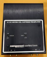
Both versions are for operating without mains power supply - just two secondary D-cells are in use.
What is the difference ?
BTW - the mains supply version uses the additional term "AC"
The difference is the year of release - the suffix "DC" means a newer series (release 1976) than the older series without that suffix (release already 1974) go to
ハイファイ堂メールマガジン
Who know the difference between the gain stage circuits of this both versions ?
The schematic of the JC-1DC (potted version), which I have create some years ago, you will find in post #8 below.
Maybe there is also a schematic of the JC-1 anywhere. Simplified schematic you will find in post #32 so as some hints concerning the question from headline.
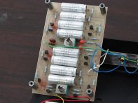
The last both pictures in post #12 are from a device in not worked condition at left channel - unfortunately also in a potted version. The replace of electrolytic capacitors by new ones don't provide the wanted success.
What is the difference ?
BTW - the mains supply version uses the additional term "AC"
The difference is the year of release - the suffix "DC" means a newer series (release 1976) than the older series without that suffix (release already 1974) go to
ハイファイ堂メールマガジン
Who know the difference between the gain stage circuits of this both versions ?
The schematic of the JC-1DC (potted version), which I have create some years ago, you will find in post #8 below.
Maybe there is also a schematic of the JC-1 anywhere. Simplified schematic you will find in post #32 so as some hints concerning the question from headline.
The last both pictures in post #12 are from a device in not worked condition at left channel - unfortunately also in a potted version. The replace of electrolytic capacitors by new ones don't provide the wanted success.
Last edited:
pictures/images
Attachments
-
 Mark Levinson JC-1 open-III.jpg31.3 KB · Views: 1,437
 -
 Mark Levinson JC-1.jpg167.8 KB · Views: 1,356
 -
 Mark Levinson JC-1-DC top open.jpg160.1 KB · Views: 1,362
 -
 Mark Levinson JC-1-DC top silver-II.jpg488.7 KB · Views: 1,375
 -
 Mark Levinson JC-1-DC top-black.jpg93.4 KB · Views: 1,304
 -
 Mark Levinson JC-1-DC top-silver.jpg139.5 KB · Views: 556
 -
 Mark Levinson JC-1-top.jpg148.9 KB · Views: 864
pictures/images
What's in the module is "secret"
Of the discrete version schematic circulates on the Net.
not for me - I had create also from the potted module from "JC-1DC" the schematic and PCB-layout and upload anywhere here on diyaudio.What's in the module is "secret"
But this wasn't the question.
Both models JC-1 and JC-1DC uses both potted and not potted modules (i. e. with not accessible parts in one case and accessible parts - as most usual - in the other case).
Thus this can't be the difference.
Last edited:
I don't know the answer.Why do you ask if you know the answer already?
What is to read in my first post?
Is my english so bad?
I know the module of the JC-1DC, but I don't know the module of the JC1. This means, that I also don't know the difference between both module models.
The JC-1DC module are also in use here:
Mc Kinnie RO III front | Flickr - Photo Sharing!
http://www.diyaudio.com/forums/solid-state/78843-john-curl-mc-kinnie-phono-pre-preamplifier.html (post #3)
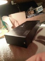
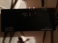
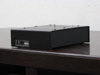
The sizes of this module are bigger than the sizes of the JC1 module (have a look to the first image of my first post).
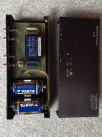
by this version of the JC-1DC there is no module inside (maybe since series II):
JC-1DC Mark Levinson ¥Þ¡¼¥¯¥ì¥Ó¥ó¥½¥ó ¹â²ÁÇã¼è¡¦ÈÎÇä ¥Ï¥¤¥Õ¥¡¥¤Æ² Ãæ¸Å¥ª¡¼¥Ç¥£¥ª/ Ãæ¸Å¥ì¥³¡¼¥É/Ãæ¸ÅCD/McIntosh/JBL/audio-technica/Jeff Rowland/Accuphase/¿¿¶õ´É¥¢¥ó¥×/¥È¥é¥ó¥¹Â¾¥ª¡¼¥Ç¥£¥ª¤Ê¤ó¤Ç¤âÇ㤤¤Þ¤¹ ²¼¼è¡¦ÄÌÈΡ¦°ÑÂ÷ÈÎÇä¤â¤ä¤ê¤Þ¤¹ 13-74607-88374-0
all components are easily accessible for replace.
some infos in the wrong thread (hard to find without navigation hints/post numbers):
http://www.diyaudio.com/forums/anal...urls-blowtorch-preamplifier-part-ii-1934.html (post #19332 and #19334)
http://www.diyaudio.com/forums/anal...urls-blowtorch-preamplifier-part-ii-4370.html (#43694)
My schematics of JC1-DC are to find on many websites over the world - e. g.
Mark Levinson JC-1DC
BTW - here a rebuild module based of the JC-2
Mark Levinson 1 - cbznob???? - Yahoo!???
Last edited:
For check I have in the moment the JC1 as to see in the first picture (post #1) but with serial number 1188.
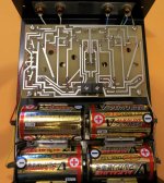
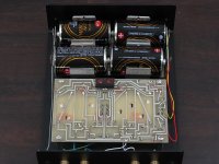
I want to replace the electrolytics. 4 pieces are outside. How many electrolytics are inside of the module?
And in which direction is allocated the potted PCB? Is the solder site on top or at bottom?
The schematic of the JC1-DC module, which I have opened at those days, is attached as PDF-file here.
Unfortunately the JC1 module isn't the same.
Thank you for advices.
Attachments
Last edited:
Faulty schematic
I dunno who designed the AC adapater schematic but I think it's wrong. You need a center-tapped transformer as the ground is not connected now.
Or alternatively use a virtual ground creator like TLE2426 as Jim Hagerman did here:
http://www.hagtech.com/pdf/piccolo2.pdf
😎
For check I have in the moment the JC1 as to see in the first picture (post #1) but with serial number 1188.
I want to replace the electrolytics. 4 pieces are outside. How many electrolytics are inside of the module?
And in which direction is allocated the potted PCB? Is the solder site on top or at bottom?
The schematic of the JC1-DC module, which I have opened at those days, is attached as PDF-file here.
Unfortunately the JC1 module isn't the same.
Thank you for advices.
I dunno who designed the AC adapater schematic but I think it's wrong. You need a center-tapped transformer as the ground is not connected now.
Or alternatively use a virtual ground creator like TLE2426 as Jim Hagerman did here:
http://www.hagtech.com/pdf/piccolo2.pdf
😎
Last edited:
In general you are right, but in case of the JC1DC the showed circuit works very fine without transformer with center tap.
I want still to know the differences between the "JC-1DC" and the "JC-1" head amp module. Still no informations?
Where is the developer of both models?
From the JC-1 module I still haven't the internal circuit.
I want still to know the differences between the "JC-1DC" and the "JC-1" head amp module. Still no informations?
Where is the developer of both models?
From the JC-1 module I still haven't the internal circuit.
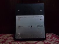
Both versions are for operating without mains power supply - just two secondary D-cells are in use.
What is the difference ?
BTW - the mains supply version uses the additional term "AC"
The difference is the year of release - the suffix "DC" means a newer series (release 1976) than the older series without that suffix (release already 1974) go to
ハイファイ堂メールマガジン
Who know the difference between the gain stage circuits of this both versions ?
The schematic of the JC-1DC (potted version), which I have create some years ago, you will find here:
Mark Levinson JC-1DC_ckt[1].
Maybe there is also a schematic of the JC-1 anywhere. The last both pictures are from a device in not worked condition at left channel - unfortunately also in a potted version. The replace of electrolytic capacitors by new ones don't provide the wanted success.
Attachments
-
 JC-1DC bottom view ser.-No 350.jpg112.1 KB · Views: 439
 -
 JC-1DC PCB solder side ser.-No 350.jpg178.3 KB · Views: 492
 -
 JC-1DC top-view ser.-No 350.jpg148.7 KB · Views: 490
 -
 JC1-DC top view ser.-No 703.jpg179.8 KB · Views: 193
 -
 JC-1DC Sticker ser.-No 703.jpg160 KB · Views: 236
 -
 JC-1DC PCB solder site ser.-No 703.jpg174.5 KB · Views: 469
 -
 JC-1DC PCB component side.jpg172.4 KB · Views: 535
 -
 JC-1 #1764 old caps.jpeg247.5 KB · Views: 476
 -
 JC-1 #1764 new caps.jpeg422.9 KB · Views: 391
Why don't you ask John Curl directly? He's a very active member here and might still remember what if anything is different between the two.

yes, but both versions are battery powered working versions.Guys,
As I remember, the DC simply stood for battery power.
Charles
If you are right, the different between "JC-1" and JC-1DC" is large. The input signal is fed in at the base, like iFi iphono2 - go toThe circuit below is also a JC design.
Maybe this was the version used in the JC-1.
This one shows 2 transistors plus two emitter resistors, but to lower the noise, JC used 8 transistors with eight emitter resistors in parallel.
Hans
iFi Audio Model "micro iPhono2": Creating Schematic - help needed
and not at the emitter like the JC1-DC (go to the attached image).
Attachments

Last edited:
I am looking for a faulty JC1 module - go to post #2, first image and
Suche Mark Levinson JC1 JC-1 MC Pre-Pre Modul in Rheinland-Pfalz - Weitersborn | Weitere Audio & Hifi Komponenten gebraucht kaufen | eBay Kleinanzeigen
maybe one of the members have any and can make an offer - thank you.
Suche Mark Levinson JC1 JC-1 MC Pre-Pre Modul in Rheinland-Pfalz - Weitersborn | Weitere Audio & Hifi Komponenten gebraucht kaufen | eBay Kleinanzeigen
maybe one of the members have any and can make an offer - thank you.
maybe the simplified schematic from the attached patent - which is more easy than those from JC-1DC - is in use in the JC-1 potted MC head amp module.
P.S.: an interesting statement from John Curl in post #19334 under
https://www.diyaudio.com/community/threads/john-curls-blowtorch-preamplifier-part-ii.146693/page-967
concerning the JC-1 I have found - I read here the follow:
The original JC-1 was actually better, subjectively, than the JC-1AC or JC-1DC which were 'improved' versions of the JC-1.
I did not know what input loading did at the time.
I did an A-B test with a JC-1AC to prove the point, subjectively.
It was unfortunate, and it shows how difficult it is to predict subjective audio quality.
Attachments
Last edited:
A bit off the record, but starting with the JC-1, I replaced the four 2*4 by two transistors having a much lower noise figure, the ZTX851 and the ZTX951.
But because the collectors are loaded by feedback component #18 in the patent scheme, this has serious impact on the open loop gain, the maximum output and the distortion.
That's why I buffered the collectors with a high speed LT6203 low noise op-amp, not deteriorating the noise at all.
And just because you don't want to have DC current flowing into the Cartridge, I also added a LT1884 Servo that is producing the positive supply.
But the basic idea is still completely there.
Noise contribution is below 0.3nV/rtHz.

You can easily increase maximum output voltage and decrease distortion even further by giving U1 a gain of 10.
Hans
But because the collectors are loaded by feedback component #18 in the patent scheme, this has serious impact on the open loop gain, the maximum output and the distortion.
That's why I buffered the collectors with a high speed LT6203 low noise op-amp, not deteriorating the noise at all.
And just because you don't want to have DC current flowing into the Cartridge, I also added a LT1884 Servo that is producing the positive supply.
But the basic idea is still completely there.
Noise contribution is below 0.3nV/rtHz.
You can easily increase maximum output voltage and decrease distortion even further by giving U1 a gain of 10.
Hans
- Home
- Source & Line
- Analogue Source
- Which differences between Mark Levinson's "JC-1" and "JC-1DC"