Sorry if this is considered as cross posting, but I guess this specific question might get more feedback in the Tubes/Valves section than in the thread over in Headphone Systems.
I am in the process of designing a push-pull amplifier for electrostatic headphones using directly heated triodes (or triode strapped pentodes) in the output stage. The goal is to swing +/-650 Vpk at a bias of approx. 20 mA or so (+/-325 Vpk swing at each tube). See here for full details.
Which DHT tubes would fit the bill?
I'm afraid neither.
Stax compatible tube device use for example ECC81 (Mu:60), ECC81, 6SN7GT (Mu:20) construction, overall gain 47-50dB.
As you discussed here , the most of DH tube's gain is too low.
Even the 841/VT-51 VAS stage (CCS loaded, with FET SF, without it almost unusable due to the enormous output impedance) has 28dB.
There will be an input/driver stage that provides the missing gain!
If the amp output is 1300 Vpp = 460 Vrms, and the input is 4 Vrms (for example a balanced output from a modern DAC), the total voltage gain of the amp would need to be approx 100x. Of course this will not all happen in the DHT output stage. The input/driver will have to take care of that.
If the amp output is 1300 Vpp = 460 Vrms, and the input is 4 Vrms (for example a balanced output from a modern DAC), the total voltage gain of the amp would need to be approx 100x. Of course this will not all happen in the DHT output stage. The input/driver will have to take care of that.
Last edited:
Considering about the life cycle of the project. I thing the common power DHTs should be the only choice.
Regardless of the dimention limitations, I think the best choise designing an electrostatic amp is 211 with plate inductor.
It's in production with several manufacturers. With μ=12 and no need of A2 operation, it's not so hard to drive. Maximum voltage swing and output current is a piece of cake for it. Since 211 needs a high anode voltage, anode CCS or gyrator could be too hard to design.
But it's bigger than any 300Bs.
The disadvantage of 801/801A series is the same as EML 20/30 series. There's only one manufacture producing it, and could be obsolete any time in the future. With only NOS tubes in the market, the life of the project will be ended soon.
Regardless of life cycle of the project and driving stage capabilities. Maybe 3C24 or 826 could be possible candidates. Both of them have enough gain and thoriated tungsten filament make sure they can work at high voltage. If Schade Feedback of Tetrodes or Pentodes are acceptable, 4-65A could be a possible candidate too.
Last edited:
There will be an input/driver stage that provides the missing gain!
If the amp output is 1300 Vpp = 460 Vrms, and the input is 4 Vrms (for example a balanced output from a modern DAC), the total voltage gain of the amp would need to be approx 100x. Of course this will not all happen in the DHT output stage. The input/driver will have to take care of that.
You still need a tube that is capable of swinging 650v peak to peak. That's harder than you realize. Even a 300b can't quite do it (although it is close).
Hmm, not sure I get this. As you say, I may be missing something.You still need a tube that is capable of swinging 650v peak to peak. That's harder than you realize.
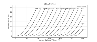
Just as an example: what's wrong with biasing an 801 tube at Ua=500 V / Ia=20 mA / Vg=-47 V (see attached curves, which I measured from a real tube)? As I see it, that would allow a swing of +/-350 Vpk, or 700 Vpp before it hits positive grid voltage.
Attachments
I see your point, but I tend to look at this from a different angle:The disadvantage of 801/801A series is the same as EML 20/30 series. There's only one manufacture producing it, and could be obsolete any time in the future. With only NOS tubes in the market, the life of the project will be ended soon.
- The 801 is available from new production, and there are quite a few 801 / 10 / VT-25 from old production out there (either used or NOS and at much lower prices than the new production tubes).
- The 20B is available from new production only (at similar prices as new-production 801). They are not available second hand.
- The 20B is a new design, which is specific for Emissionlabs. What would happen if Emissionlabs stops existing? Will another company pick this up and make 20B tubes? Will the EML 20B tubes be available second hand?
801 tube
What's wrong with A2?... before it hits positive grid voltage.
Transmitter tubes as 801a really "likes" grid current mode.

Beefy driver (for example CF or SF) needed, which capable to drive 801a grid with -even- 15..25mA current peek.
Good point. Nothing wrong with A2 in principle. With A2, the 801 could be biased at around 350 V / 20 mA and still swing +/-325 Vpk. The lower bias voltage with the A2 option would also open the door to using the 10Y / VT-25, which don't like biasing at 500 V. As you wrote, the drawback might be that A2 needs an extra buffer to drive the grid positive.
What would be better, easier, preferable, etc.?
What would be better, easier, preferable, etc.?
- A1 with no need for a buffer, biased at 500 V / 20 mA
- A2 with the extra buffer but at lower bias voltage (350 V / 20 mA)?
Unfortunately, the good chokes are very problematic parts. They must conduct a lot of anode (idle) current. The wire must be relative beefy, the number of turns must be enough for good low freq. extension. Must be low stray (shunt) capacitance. The twin choke will be large (same as OPT). Difficult, but beautiful design challenge.with plate inductor
As happy side effect is rock-solid DC-biasing, without risk of thermal runaway.Beefy driver (for example CF or SF) needed

Agree. Apart from your points, chokes like to pick up hum. Been there, done that. As described in the main thread (link in first post), the amp will use CCS/gyrator loads, not a real choke.Unfortunately, the good chokes are very problematic parts.
These operating points not optimal for 801a.What would be better, easier, preferable, etc.?
- A1 with no need for a buffer, biased at 500 V / 20 mA
- A2 with the extra buffer but at lower bias voltage (350 V / 20 mA)?
If you want acceptable distortion (at high anode swing), must to push this tube to near (80-90%) maximum dissipation.
I use its at about 18W dissipation.
Samples:
The A1 version requires 10k anode load, and lower grid swing.
The A2 at 3k3 load produces higher distortion, but requires lower B+ ... with higher current.
In this case (where output power is negligible) I prefer the first version.


Hmm, not sure I get this. As you say, I may be missing something.
Just as an example: what's wrong with biasing an 801 tube at Ua=500 V / Ia=20 mA / Vg=-47 V (see attached curves, which I measured from a real tube)? As I see it, that would allow a swing of +/-350 Vpk, or 700 Vpp before it hits positive grid voltage.
801a would do it, but they are spendy. Last time I saw a quad matched set on ebay they went for almost 1000 usd.
The idea of such amplifier is very attractive, but implementation for pro-biased STAX models poses insurmountable challenges. Just imagining a pair of 211s with a kilovolt supply to produce few milliwatts of power would hopelessly frustrate me.
However, for vintage STAX with 230 V bias this is quite practicable. I am working on a PP amplifier with a pair of 1P24B-EV loaded with a CT audio choke. B+ is 250V, idle current 15 mA per tube. The load choke has two separate components for low and high frequencies. The LF part is a PP 6BQ5 output transformer from Hammond organ, chosen for its highest inductance (about 200H), secondary winding removed. The HF part is custom wound on supermalloy EI-57 core, with highly sectioned winding wound with silk-clad magnet wire. The chokes are connected in series. B+ is supplied to CT by a current source (choke), which enforces strict class A operation. Voltage amplification stage is 1:12 step-up input transformer.
However, for vintage STAX with 230 V bias this is quite practicable. I am working on a PP amplifier with a pair of 1P24B-EV loaded with a CT audio choke. B+ is 250V, idle current 15 mA per tube. The load choke has two separate components for low and high frequencies. The LF part is a PP 6BQ5 output transformer from Hammond organ, chosen for its highest inductance (about 200H), secondary winding removed. The HF part is custom wound on supermalloy EI-57 core, with highly sectioned winding wound with silk-clad magnet wire. The chokes are connected in series. B+ is supplied to CT by a current source (choke), which enforces strict class A operation. Voltage amplification stage is 1:12 step-up input transformer.
Last edited:
Following this thread with interest.
I'm currently on a similar trip, but with the Jecklin 'phones; I have 2 pairs, 1 in good standing and plays wonderful in spite of the original but less than perfect transformers; the other pair needs re-foaming, no big deal. The bias for these is 1.5KV with a 10G load, quite a bit more than the Stax.
I've bought a bunch of 6S4A I hope will do the trick.
This is the required op.point implementation.
- A1 with no need for a buffer, biased at 500 V / 20 mA

Your SPICE simulation are interesting, but they seem to assume a resistive anode load and a resistive speaker load through a transformer. The estat amp will use CCS anode loads and the estat load is mostly a capacitor. See here (link also in first post): https://www.diyaudio.com/community/threads/open-source-dht-estat-headphone-amp-osdeha.407679/These operating points not optimal for 801a.
If you want acceptable distortion
How does the bias voltage play a role for the audio output of the amp? The bias voltage for the estat will be separate from the audio circuit.The idea of such amplifier is very attractive, but implementation for pro-biased STAX models poses insurmountable challenges.
Am I missing something?
Last edited:
That's just what I mean. There're a few second hand and NOS 801As existing in the market. While ER801A is still in production. That's why 801A is considered to be a better choice comparing with 20/30 series from EML. But ELROG has similar situation. If ELROG stop producing 801A, I don't think the inventory in second hand market can still be such a low price. The total amount of 801A is definitely more than EML 20/30, but it's still too few. All these types turned to be Not Recommended for New Design when comparing with 211, which is available from so many manufactures.
- The 801 is available from new production, and there are quite a few 801 / 10 / VT-25 from old production out there (either used or NOS and at much lower prices than the new production tubes).
- The 20B is available from new production only (at similar prices as new-production 801). They are not available second hand.
- The 20B is a new design, which is specific for Emissionlabs. What would happen if Emissionlabs stops existing? Will another company pick this up and make 20B tubes? Will the EML 20B tubes be available second hand?
If I'm considering building such a project. Suppose it to be my last amplifier with my last headphone, I'll have these questions on the power tube.
How much for a set of power tubes?
How long can a set of tubes work?
How much will a set of tubes be when I have to buy a new set?
Can I still get new matched tubes 10 years later?
These questions actually focus on How long can the project work for me. And how much I should pay for its further maintenance.
It seems that a set of EML 20/30 can last longer than 801A due to the filament material?
I think a Stand-By mode with Constant Current Filament should be applied to maximize the life span of the power tube.
LL2743 and LL1667 could be possible candidates for anode choke. Configured in Push Pull mode with minimum core air gap, both of them can provide over 1300Vpp @ 30Hz and enough primary inductance for good LF response. They're not so large, but the shunt capacitance still need to be measured.the good chokes are very problematic parts. They must conduct a lot of anode (idle) current. The wire must be relative beefy, the number of turns must be enough for good low freq. extension. Must be low stray (shunt) capacitance. The twin choke will be large (same as OPT). Difficult, but beautiful design challenge.
In the proposed scheme, the B+ voltage serves as polarizing voltage by connecting membrane to ground via a megohm resistor. Of course, polarizing voltage may be boosted from additional negative voltage source.How does the bias voltage play a role for the audio output of the amp? The bias voltage for the estat will be separate from the audio circuit.
Am I missing something?
With sensitivity about 100 dB at 100 Vrms, why do you need 650 V peak-to-peak? At 100 dB SPL, hearing can be lost in 15 min according to OSHA standards. I personally cannot tolerate anything over 80-85 dB.
- Home
- Amplifiers
- Tubes / Valves
- Which DHT tubes for an electrostatic tube amp?