Hi all,
I have to make a choice between two chip amps I have, to build my first amp. 😕 😕
The first is a Sanyo STK4412:
20Wx2 (f=1kHz, 8ohms, THD 1.0%)
10Wx2 (f=30Hz-20kHz, 8ohms, THD 1.0%)
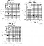
0.3% THD (P=0.1W, 8ohms, f=1kHz) see graph attached.
STK4412 datasheet
The second is a National LM1876:
20Wx2 (f=1kHz, 8ohms, THD 0.1%+N)
0.08% THD (P=15W, 8ohms, f=20Hz-20kHz) see graph attached
LM1876 datasheet
I have all the components for the STK including transformer but if i'm going for the LM, i will have to buy new transformer plus components, etc. Would it really be worth the extra spending to get that 0.1% THD of the LM or would the difference be insignificant.
Any thoughts much appreciated , thanks 🙂
I have to make a choice between two chip amps I have, to build my first amp. 😕 😕
The first is a Sanyo STK4412:
20Wx2 (f=1kHz, 8ohms, THD 1.0%)
10Wx2 (f=30Hz-20kHz, 8ohms, THD 1.0%)
0.3% THD (P=0.1W, 8ohms, f=1kHz) see graph attached.
STK4412 datasheet
The second is a National LM1876:
20Wx2 (f=1kHz, 8ohms, THD 0.1%+N)
0.08% THD (P=15W, 8ohms, f=20Hz-20kHz) see graph attached
LM1876 datasheet
I have all the components for the STK including transformer but if i'm going for the LM, i will have to buy new transformer plus components, etc. Would it really be worth the extra spending to get that 0.1% THD of the LM or would the difference be insignificant.
Any thoughts much appreciated , thanks 🙂
Attachments

I say go for the STK,since you already have all the parts..If you don't like it,build up the LM chip later on. 🙂
I actually built an amp with the STK4412 a few years ago,From what I recall,it wasn't too bad. I just used the plain datasheet circuit,with some tweaking it might be pretty good.
I actually built an amp with the STK4412 a few years ago,From what I recall,it wasn't too bad. I just used the plain datasheet circuit,with some tweaking it might be pretty good.
I doubt you would have to change transformers and get different parts; the example circuit in the STK is shown as single-supply, but looking at the functional schematic it has just about the full pinout of a dual supply power opamp, so you can build it to a typical LMxxxx gainclone schematic. It's really just a bad datasheet.
ok, thank you for your replies.
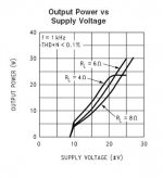
On another note, i noticed the LM1876 claims to output 40W per channel (1%thd, 8 ohms) when V+/- is above ~30V. See the graph below. Is this feasible for a chip originally rated at 20Wx2?
On another note, i noticed the LM1876 claims to output 40W per channel (1%thd, 8 ohms) when V+/- is above ~30V. See the graph below. Is this feasible for a chip originally rated at 20Wx2?
Attachments

Last edited:
Hi,
those excessive distortion graphs (1% & 10%) show that these devices can amplify to those powers without destroying themselves. But that is not an indication of quality.
Expect a maximum of ~35W into 8ohms @ 0.1% distortion at the supply voltage maxima shown.
If you want that power, then choose a PSU that can supply the required on load voltages.
But ensure the PSU voltage offload is below the absolute maximum for the chipamp.
hi andrew,
i had a closer look at the datasheet and it actually gives a power out vs supply voltage graph for 0.1% THD (f=1kHz). For an 8 ohm load it goes up to 30W at around +/-27Volts. But the graph stops after this point. Could this be an indication of an upper limit for supply voltage? Btw, the absolute maximum voltage is at 64V (ie: +/-32V)
i had a closer look at the datasheet and it actually gives a power out vs supply voltage graph for 0.1% THD (f=1kHz). For an 8 ohm load it goes up to 30W at around +/-27Volts. But the graph stops after this point. Could this be an indication of an upper limit for supply voltage? Btw, the absolute maximum voltage is at 64V (ie: +/-32V)
Attachments
you have to work back from that specified maximum operating voltage.
I would start with mains at maximum tolerance find the maximum AC voltage for the +-32Vdc and using the regulation of my chosen transformer and normal mains voltage find the normal AC & DC voltages into and out of the PSU.
That let's me specify the AC voltages of the transformer. I would expect 240:20.5Vac 5% regulation for my 240Vac supply.
Most transformers are specified for 115/230Vac. That brings down the AC to just 19.8Vac when used on a 240Vac supply.
I would choose a 230:18+18Vac transformer with lowish regulation (5 to 8%). This will give me an absolute maximum of +-30Vdc when mains is at 254Vac and regulation is 8%.
If I wanted to squeeze a bit more from the amplifier, I might think about (but reject the idea) adding a few turns to make this a 19+19Vac transformer.
Now that I have my safe Vac I can use the chosen transformer at my normal voltage (~239 to 245Vac). Subtract about 4Volts for voltage sag on short term full power testing. Looking at the graph I see ~28W for +-26Vdc.
Summarising, a 230:18+18Vac 8% regulation transformer powering an 1876 from 240Vac gives ~28W into 8ohms.
Last edited:
Thanks, that cleared things up a lot.
I take it that it would be similar for the STK which i have already running. I currently have the supply voltage at 42.5Vdc (single rail). The chip has an absolute max rating of 56V (39V recomended). The AC input from the transformer is at 31.5Vac.
I assume that there is not much more room for increasing the power output of the chip further by incresing suppy voltage (Allowing for voltage sag, abosulute maximum of transformer,etc). Is it correct.
And how did you calculate the absolute maximum of -/+30Vdc for a 230:18+18Vac transformer (what is 254V?) isnt it usually 18Vac x 1.414 - diode rectifier drop
Last edited:
the 240Vac mains supply system has upper and lower voltage limits (tolerance) of 254Vac and 216Vac.
The open circuit output voltage of a transformer is mains voltage / rated primary voltage * rated secondary voltage * [1+regulation]
for a 242Vac supply into a 230:18+18Vac 5% regulation transformer this comes to 242/230*18*(1.05) = 19.89Vac.
The peak voltage on the smoothing caps with near zero loading is ~sqrt(2) * Vac - diode Vf (0) = [1.414*19.89]-0.5=27.6Vdc
A 5% reg, 230:18+18Vac transformer running on 242Vac, the smoothing caps will have +-27.6Vdc on them.
Now do the numbers for your mains' supply tolerance and for the rated voltages of your proposed transformer.
ok my plan is to increase the supply voltage of my STK (currently at 42V)
My transformer has two secondary windings, one (currently used) which is at 33Vac (31.5v when loaded) and another winding at 15Vac.
If i combine the two, i can get ~48Vac and when converted to DC (1.414*48-0.5) gives approx 67Vdc.
And then using some zener diodes bring the voltage down to approx 50VDC.
Does this idea sound practical (i.e.: joining the two windings together and using zener diodes to reduce voltage?)
Hi,
yes you can series connect two transformer secondaries.
The maximum current, both continuous and transient, is limited by the current capability of the lower rated winding.
67Vdc down to 50Vdc requires a Vdrop of 17Volts.
If your average current draw is 1A that requires 17W of dissipation in the dropping device. Zeners will not do this. A transistor assisted Zener can, but you will need quite a big heatsink.
i decided to test it out before i buy the components for the voltage increase.
I tied both secondary windings together (33V+15Vac=~48Vac) and I put a 12W 12V light bulb in series with the power supply to the STK (the voltage varied between 62VDC and 52Vdc with volume, during testing. (I know its not ideal but did it just for checking how it sounds).
I thought it didn't make much difference to overall sound (may have gained a few watts) but no major difference. If anything it sounded more distorted.
So i have decided to leave the supply at 42Vdc and increase the input line voltage (may be use preamp circuit) to see if it makes anything noticable diffference. Will post results soon.
I tied both secondary windings together (33V+15Vac=~48Vac) and I put a 12W 12V light bulb in series with the power supply to the STK (the voltage varied between 62VDC and 52Vdc with volume, during testing. (I know its not ideal but did it just for checking how it sounds).
That 15 V winding was probably not designed for high current output, so that test was more likely to result in burnt secondaries than in higher power or better sound. The light bulb in series with the STK must have saved them.
It must also have reduced the voltage at the STK's pins exactly when it was most inconvenient. When that bulb is fully lit at about 1 A, it will have 12 Ohms. 12 Ohms in series with an 8 Ohm load means you get only 40 % of the voltage at the speaker terminals. Instead of increasing the output power you limited it. And if the light bulb never lit up during the test, you were far from the maximum power output. Then you should either increase the line voltage or, easier, increases the STK's gain.
I thought it didn't make much difference to overall sound (may have gained a few watts) but no major difference.
That is the point. Higher voltage will only give you more power = more SPL. If you want better sound, you need a different amplifier or, more likely, different speakers.
- Status
- Not open for further replies.
- Home
- Amplifiers
- Chip Amps
- Which chip amp to use :eek: