I have two choices here.
1. Online Shop HIMING RIVALS FU50 Bluetooth tube amplifier Headphone amp HIFI EXQUIS Signal-ended lamp amps FU-50 luxury version | Aliexpress Mobile
That amp has multiple inputs which I like and bluetooth compatibility.
It has 3+1 transformers inside and 4 big electrolytic capacitors. I will attach a picture of the inside. It will cost me 430$ CAD shipped.
2. Is this beauty
Online Shop 2017 New Handmade HiFi 6P1 Vacuum Tube Integrated Amplifier Stereo Single-ended Class A HeadphoneAmp Black | Aliexpress Mobile
I has only 2 electrolytic capacitors. Doesn't have multiple inputs. No bluetooth. But It does have 2 more tubes and my favorite tubes are a direct fit (6Sn7). It looks better imho.Shipping price is 360$CAD with shipping.
I'm leaning towards the second one because of my gut feeling but I really want multiple inputs and bluetooth. I plan on modding the one i choose with better caps and adding filter caps etc.
So which one is the better buy in your opinion?
Attachments
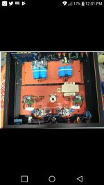
The first has a typo on the front panel (SPEKER !?!?!) - Never a good indicator for a quality build, and the internal wiring is a bit messy.
The second is not very tidy inside, but there should be scope to improve it if needed. It claims an inout impedance of 100 ohms which is almost certainly meant to be something like 100k ohms.
Both come with some pretty suspect marketing text. I've not bought products like this from China - people here have varying experiences, good and bad.
If I had to choose one of these then I would pick the second, but I'd ask the supplier for a schematic first if possible so that I knew more about what I was buying. Personally I would choose neither - they look too much like home-made hobby projects. Nothing wrong with that except that they are being sold as somefing better.
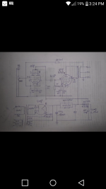
It’s missing a resistor for the negative feedback network.
Well that sounds great... I wish I knew more about schematics and what a Negatuve Feedback Network is.
Not only that - it feeds onto a cathode with a bypass capacitor to ground. Not good. Biasing the grid of the input valve via the pot is also generally not the best way to do it, even if commonly done in budget designs. I hate China bashing since it is often ill-deserved, however, this looks like a typical design thrown together without a clear understanding how it really works.It’s missing a resistor for the negative feedback network.
Jazbo8 was right.
And the others too, who chimed in before I finished my edits.
How can we trust a schematic that is incorrect?
The 10k Ohm negative feedback resistor is trying to drive the cathode bypass cap.
It is important to fix this because the amp output is in pentode mode, so negative feedback is necessary.
If it is wired as in the schematic, a resistor could be added between the bottom of the input tubes cathode 'self bias resistor and bypass cap combo' and ground. The 10k feedback would connect at the junction of the bias circuit and the added resistor.
But once you get negative feedback 'wired properly' if it never was tested that way, it might oscillate because of too much feedback, output transformer phase shift, wrong phase wiring of the transformer output (wires can be swapped for correct phase).
Also, it looks like the first B+ cap is 450uF (schematic is hard to read).
450uF gives a rectifier tube a Very hard time, far too much capacitance (gives lower hum, but how long can the rectifier go before it is destroyed).
Last edited:
And how about 4 grid stopper resistors, one for each grid of the input tubes; and 2 grid stopper resistors, one for each output tube?
Hmmm, it sounds like we are designing an amplifier.
I can hardly wait to see the schematic of the second amplifier.
You want multiple inputs and bluetooth compatibility, right?
Are you intending to stream music through a bluetooth device to an amp that has a bluetooth receiver?
Hmmm, it sounds like we are designing an amplifier.
I can hardly wait to see the schematic of the second amplifier.
You want multiple inputs and bluetooth compatibility, right?
Are you intending to stream music through a bluetooth device to an amp that has a bluetooth receiver?
The second amp appears to have a choke in the B+ power supply.
The first amp only had resistors instead of a choke.
Some kind of RCA switcher could work.
But who knows of a stand alone bluetooth receiver that puts out audio?
Does your smartphone have an earphone output, and what kind of connector is it? (unique or standard type)?
The first amp only had resistors instead of a choke.
Some kind of RCA switcher could work.
But who knows of a stand alone bluetooth receiver that puts out audio?
Does your smartphone have an earphone output, and what kind of connector is it? (unique or standard type)?
- Status
- This old topic is closed. If you want to reopen this topic, contact a moderator using the "Report Post" button.
- Home
- Amplifiers
- Tubes / Valves
- Which chinese amp should I go for ?