Yep, I know, that's why I tried to come up with a baffle that's only a bit wider than the driver 🙂 It's not the baffle width that's the issue, it's the depth of that small 'roundover' on the front, I think. I think I'm getting a reflection off that edge. I've tried the driver nude, and that works fine, but of course looks kinda ugly.
I don't seem to have the null with my tweeters & all I've got at this stage is a 45 degree chamfer around them.
I might be wrong, but I thought the narrower the baffle, the more extended the uniformity of directivity, ie narrower is better
eg Rudolf/ twest/ cuibono/ gainphile could confirm/ correct . .
Cheers
Yes you are right, that is the theory I have been working to, hence the design.
If you want to know the *maximum SPL of a dipole at the low Hz, Linkwitz's site http://www.linkwitzlab.com/faq.htm#Q14 has a spreadsheet for calculating it based on:
[*] driver surface area,
[*] Xmax and
[*] baffle dimension D
I cant upload it, but I put the values in for the AE Dipole 15s
It's minimum Hz at maximum SPL of say 100 dB, limited Xmax is c 40 Hz.
If you want more dB below that, a box is needed . .
[*] driver surface area,
[*] Xmax and
[*] baffle dimension D
I cant upload it, but I put the values in for the AE Dipole 15s
It's minimum Hz at maximum SPL of say 100 dB, limited Xmax is c 40 Hz.
If you want more dB below that, a box is needed . .
Last edited:
Yeah I was wondering about that when I saw your photo. Are you using the PRD or plain version? Do you have a chamfer on the back too? If you could post close-up photos of the front and back tweeter mount, that would be helpful. It's entirely possible that my diagnosis for the source of my response null is incorrect.I don't seem to have the null with my tweeters & all I've got at this stage is a 45 degree chamfer around them.
What I was thinking for my back burner Neo3+Neo10 in integrated Le Cleac'h waveguide project was CNCing front and rear halves and enclosing the drivers with a press fit of the halves. The result's a clamshell type mounting where the only required surface discontinuities are counterunk screw heads on the rear waveguide (though routing channels for the cables inside the waveguide takes some attentive design). For the Neo3 two screws would probably be enough with most materials.I might try counter-sinking it from the front, which will leave exposed screw heads, but I don't see a way around that.
A quick version of this is to cut/mill/route dowel/ABS/some other cylindrical material to press fit onto the sides. Bring the inside edges in adjacent to the punched holes and you have something which starts to approximate an OS throat.
Yeah, I thought about the 2-half baffle. My friend's CNC isn't currently set up to accurately cut on both sides of a sheet, so I hadn't really explored designs which would require that.
There was someone on HTGuide that experimented with PVC/ABS pipe cut at 45 degree angles and glued together to form a front and back waveguide. I might try something like that too.
There was someone on HTGuide that experimented with PVC/ABS pipe cut at 45 degree angles and glued together to form a front and back waveguide. I might try something like that too.
Mids & tweets in an integrated waveguide? Sounds interesting 
T and/ or S,
Do you have any visuals: eg a drawing, a link
T and/ or S,
Do you have any visuals: eg a drawing, a link
Since it's a back burner project I haven't calculated profiles yet. In the meantime, see the Geddes on Waveguides and Jean-Michel on Waveguides threads in this forum for OS and Le Cleac'h profiles, respectively. In particular, mige0's horizontal dipole horn's in the Le Cleac'h thread.
A search on HTGuide should find Craig's Neo3 waveguide (at least IIRC it was Craig).
A search on HTGuide should find Craig's Neo3 waveguide (at least IIRC it was Craig).
Since it's a back burner project I haven't calculated profiles yet. In the meantime, see the Geddes on Waveguides and Jean-Michel on Waveguides threads in this forum for OS and Le Cleac'h profiles, respectively. In particular, mige0's horizontal dipole horn's in the Le Cleac'h thread.
A search on HTGuide should find Craig's Neo3 waveguide (at least IIRC it was Craig).
Thanks Todd
I found Craig's Neo3 waveguide: looks a neat simple method
Also found mige0's horizontal dipole horn write up. . but didn't really follow it . .
I'd think the benefits, as with horn loading a conventional driver, are a boost to overall sensitivity (guess about + 3 dB), and a larger boost below its lower roll-off, ie it also lowers the potential lower XO Hz somewhat . .
Craig used 1.25" 30 mm diameter PVC tube. I'd think larger diameter tube - waveguide would increase the benefit
Last edited:
All I have are the photos I posted earlier in this thread:
http://www.diyaudio.com/forums/multi-way/186212-bohlender-graebener-neo3-2.html#post2527354
It's just a 1/4" roundover bit on a router, so it's not a calculated WG profile by any stretch 🙂 As DQ828 said, maybe a chamfer would have been better.
http://www.diyaudio.com/forums/multi-way/186212-bohlender-graebener-neo3-2.html#post2527354
It's just a 1/4" roundover bit on a router, so it's not a calculated WG profile by any stretch 🙂 As DQ828 said, maybe a chamfer would have been better.
The benefit of CNCing front and rear halves have over Craig’s simple splitting of tube, would be a more optimal waveguide shape?
It’s premature, but maybe a small group buy for Neo3 & Neo10 waveguides could eventuate??
It’s premature, but maybe a small group buy for Neo3 & Neo10 waveguides could eventuate??
Correct, other than at waveguide lengths efficiency increase and bass extension are negligible. If you want those you'll need to look at horns and deal with the attendent complication of increased mid to tweeter separation---waveguides are primarily of interest for mitigating dipole bloom by introducing a greater range of front to back path lengths at lower diffraction than what's naturally available in a small planar driver like the Neo3.
Personally I'm skeptical there's much return on investment to be had which is why it's a back burner project for me. But it's an interesting space to tinker with and a good excuse to mess about with the mill.
Personally I'm skeptical there's much return on investment to be had which is why it's a back burner project for me. But it's an interesting space to tinker with and a good excuse to mess about with the mill.
For this sort of “group buy” obviously the main cost is the developer’s time:
I might be prepared to pay a multiple of material costs, five? ten times, depending on results 😉
Thanks,
Richard
I might be prepared to pay a multiple of material costs, five? ten times, depending on results 😉
Thanks,
Richard
The various AxiDriver sims in the horn threads suggest a 5cm radius provides reasonable diffraction control with 10cm being better. Changing profiles on a 5mm scale isn't going to do much except maybe up around 20kHz where the roundover's starting to get accoustically large. It would, however, be interesting to put 1cm radius cylinders on the sides---about as small as will fit without machining down the Neo3 flange---and see if there's a noticeable difference. That approach is likely more significant than a baffle roundover as it's changing the boundary condition at the throat.It's just a 1/4" roundover bit on a router, so it's not a calculated WG profile by any stretch 🙂 As DQ828 said, maybe a chamfer would have been better.
A more natural size for the Neo3 is a 2cm radius which injects an extra 8cm or so of path length. That should move the dipole peak down from 3.5kHz nude down to 1.9kHz. Will make the blooming worse unless the increased smoothness and range of path length variation more than compensates for the closer spacing between dipole nulls. This is part of why Le Cleac'h profiles are interesting---they're natually 360+ degree whereas OS leaves 270 degrees from front to back unspecified. Le Cleac'h also allows a greater depth for a given width than OS and hence offers a bit more loading.
What I was thinking for my back burner Neo3+Neo10 in integrated Le Cleac'h waveguide project was CNCing front and rear halves and enclosing the drivers with a press fit of the halves. The result's a clamshell type mounting where the only required surface discontinuities are counterunk screw heads on the rear waveguide (though routing channels for the cables inside the waveguide takes some attentive design). For the Neo3 two screws would probably be enough with most materials.
yeah thats basically what I did, how to hide the fixings (for the two halves) or make then look ok is the challenge. Except I did the CNC the hard way for the prototype, at home with the router 🙂
Last edited:
I did some measurements on Neo's: http://www.diyaudio.com/forums/mult...nder-graebener-neo3w-neo3pdr-dipole-mode.html
Hello,Craig used 1.25" 30 mm diameter PVC tube. I'd think larger diameter tube - waveguide would increase the benefit
I made the first "waveguide" out of 1.5" pvc because I had read that JohnK used a 3/4" round over for his waveguide in his NaO Note. I guessed that John used a 3/4" inside + 3/4 outside round over = 1.5". When I installed the bigger tweeter/waveguide on the baffle it was way too wide, and I felt (as I understood it) defeated the point of a narrow baffle and avoiding dipole bloom. I guess it's all about compromises.
Unfortunately, I've recently broken my heel and can't hop around and get additional off axis measurements. I'd probably bounce the mic around too much to get accurate measurements anyway.
Here is an on axis measurement at 1 meter, mic located between tweeter and upper-mid of my attempt at a NaO Note clone. IMHO, JohnK's Note has to sound very nice.
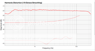
Craig
Last edited:
- Status
- Not open for further replies.
- Home
- Loudspeakers
- Multi-Way
- Which Bohlender Graebener Neo3?