... reading Xenover, very silly question 😱 but what unity of measure does he use to get 16k resistor ?
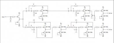
"Schematic 2 shows a 6dB/octave high pass filter, based on the buffer shown in schematic 1. The filter is comprised of C1 and R6. Calculate the values by choosing a crossover frequency and a value for C1, then calculate R6 with the following formula:
R6 = 1/(2*П*F*C1)
W
R6 is the chosen resistor value.
F is the desired crossover frequency.
If your calculator doesn't have a PI button, 3.14159 will give you more accuracy than you're likely to need.
Let us assume you want a crossover point at 1 kHz. We'll also assume that you want to use a .01uF capacitor. That yields a value of 15915 Ohms for R6."
Even if I use Khz for frenquencies and microfarad for capacitor, I have R6=16ohm.
use ohms, Farads and Hz.............
R6 = 1/(2*П*F*C1)
.....................
Even if I use Khz for frenquencies and microfarad for capacitor, I have R6=16ohm.
The numbers work out correctly:
R6 = 1/{2*3.14*1000Hz*0.00000001F} = 15915.xxx ohms
0.01uF = 10nF = 10* (10^-9)F
n = nano = 10^-9, use the Exp function of many calculators including that provided in Windows.
Some calculators require the -(minus sign) to be entered before the "9" and others, after typing the "9".
use ohms, Farads and Hz
The numbers work out correctly:
R6 = 1/{2*3.14*1000Hz*0.00000001F} = 15915.xxx ohms
0.01uF = 10nF = 10* (10^-9)F
n = nano = 10^-9, use the Exp function of many calculators including that provided in Windows.
Some calculators require the -(minus sign) to be entered before the "9" and others, after typing the "9".
... 😱 quite obvious.
🙂
That is where i'd go. The thread was inspired by an initial suggestion i made, i haven't followed the thread but it is as i understand it a buffered PLLXO.
dave
If I'm not wrong, Xenover is a PLLXO placed between buffers, B1XO is somehow different...
Attachments

Last edited:
...mmmh... maybe they are similar circuits unless transistors 😱
Anyway I am calculating C and R for 24db/oct LR. I think I will try with DCB1XO and post there my questions...
Thank you for the support!
Anyway I am calculating C and R for 24db/oct LR. I think I will try with DCB1XO and post there my questions...
Thank you for the support!
If I'm not wrong, Xenover is a PLLXO placed between buffers, B1XO is somehow different...
Neither of the 2 schema shown as buffered PLLXO. The feedback loop reaches back into the filter components.
A buffered PLLXO would be a 1st order filter with a follower before and after,
dave
A buffered PLLXO would be a 1st order filter with a follower before and after
Without feedback it wouldn't be possible to do any filter sections with a Q above 0.5 using RC filtering. One would need bufffered LC filters to do things like LR4 etc when feedback is to be avoided.
Regards
Charles
Sorry to revive this... but I am curious:
- is the B1 based crossover built around the B1 as designed by NP? If i had two B1 PCBs, would I be off to a good start or do i need a different approach?
- is the B1 based crossover built around the B1 as designed by NP? If i had two B1 PCBs, would I be off to a good start or do i need a different approach?
A good idea would be using a digital crossover.
Oh sorry... I should have stated, I am looking for analogue - hence my interest in B1
Sounds like the FW B4 or B5 might be a more appropriate design by NP, as they are specifically designed as XOs, with from my brief reading, substantial flexibility, and well, it's a Pass design, so ...
There may even be authorized PCB or kits, such as the Mesmerize for B1?
There may even be authorized PCB or kits, such as the Mesmerize for B1?
if you use a standard B1 for each jFET follower in a crossover, the whole package is going to become enormous.Sorry to revive this... but I am curious:
- is the B1 based crossover built around the B1 as designed by NP? If i had two B1 PCBs, would I be off to a good start or do i need a different approach?
A simple 2way crossover just implementing the electrical B2 or LR2 will need:
an input buffer, a low pass B2 follower, a high pass B2 follower and at least one output Buffer.
That adds up to two B1 PCBs for each channel.
B4 or LR4 will increase that by another B1 PCB. Then EQ will be added.
The jFET follower is just two transistors.
You can fit a few of them into a square inch of PCB.
Last edited:
Thanks Andrew.
I've had it drilled into my head that opamps are bad, which some say is old school thinking. That's where my interest in a jFet based crossover comes in. I have boards from Linkwitz, but am not keen on using them at this point. I intend to breadboard a XO and experiment, just not sure where to start.
I've had it drilled into my head that opamps are bad, which some say is old school thinking. That's where my interest in a jFet based crossover comes in. I have boards from Linkwitz, but am not keen on using them at this point. I intend to breadboard a XO and experiment, just not sure where to start.
- Status
- Not open for further replies.
- Home
- Loudspeakers
- Multi-Way
- Which active crossover ?