For all you engineering theoretical types out there...
I am visualizing a novel "no-touch", non-auditory (no microphone), woofer servo-feedback circuit that monitors the real-time linear motion of a speaker diaphragm. I want to capture the motion of the diaphragm returning a portion of the inverted electrical output of the sensor back to the amplifier.
The goal here is to reduce the distortion at the output by dampening the non-linear ringing and harmonic components at the output.
To this end, I have question(s):
How well does the motion of the diaphragm reflect the amplitude and frequency response of the electric signal from the amplifier? I am aware of phase shift, group delay, and frequency response nonlinearities are introduced by the speaker due to mass, stiffness, and inductive components. I am guessing that using the motion of the loudspeaker in a feedback loop would be as difficult and unstable to implement as ANR would be in a headset... but I am still hoping that a "no-touch" system monitoring the diaphragm will add little or no additional delay to the feedback loop making it easier to control the feedback response over a wider bandwidth.
I am SURE this has been attempted many times before as I have read Patents using microphones near the speaker many years ago, but why isn't servo feedback referenced from the loudspeaker in more widespread use? Maybe someone can slap me up side the head and put some sense back in before I get too deep into it.
Last edited:
Accelerometers are typically used, rather than a positional feedback. How are you thinking of sensing cone position? Lidar?
Sound pressure from the speaker is a function of the cone velocity. The accelerometer sensing systems integrate of the accelerometer output to get velocity. I haven't done one, but there's plenty of stuff out there. Velodyne starting doing feedback from the woofer cone in their subwoofers decades ago. Several manufacturers, and probably several diy'ers have done the same.
Sound pressure from the speaker is a function of the cone velocity. The accelerometer sensing systems integrate of the accelerometer output to get velocity. I haven't done one, but there's plenty of stuff out there. Velodyne starting doing feedback from the woofer cone in their subwoofers decades ago. Several manufacturers, and probably several diy'ers have done the same.
An accelerometer is definitely a "touch" sensor and has traditionally had far too much mass to consider as viable. However, it is now more viable today with the new generation of MEMS units available in very miniature dimensions.
I haven't considered LIDAR. I don't know much about how the image is processed, but it could be possible if a velocity component is readily available in the data. That's out of my area of expertise.
I haven't considered LIDAR. I don't know much about how the image is processed, but it could be possible if a velocity component is readily available in the data. That's out of my area of expertise.
Last edited:
That's not what he wants. Your idea only puts the speaker driver signal in the feedback loop, he wants the acoustic output in the loop.
It has been tried many times, under the name of 'motional feedback'. It can be done, but the large delays and phase shifts between the electrical drive signal and the acoustic output limit it to max 500Hz or so. Above that, you can't keep it stable. Nevertheless, for the bass region, it can be very effective.
Jan
Grimm Audio / Tentlabs have developed a digital motional feedback subwoofer said to lower LF distortion by 30dB.
LS1s-dmf | Grimm Audio
Jan
LS1s-dmf | Grimm Audio
Jan
As Jan points out, the idea will only work for low frequencies. I think it is a complex and expensive system that does not make enough audible difference.
Sound pressure from the speaker is a function of the cone velocity.
Sound pressure is a function of acceleration of the cone.
A velocity sensing system derives the sensed velocity to get a linear sound pressure from the cone.That's what is said in the 340 Mb, 1236 files documentation I collected on the subject of servoing drivers.The accelerometer sensing systems integrate of the accelerometer output to get velocity.
No, SPL is caused by the cone's velocity. A fixed velocity creates a DC pressure. A variable velocity creates a variable pressure (sound). I have done current sensing and accelerometer based subwoofer systems, as experiments for possible products for an audio company I used to work for.
Also, your post is confusing:
"Sound pressure is a function of acceleration of the cone."
is then contradicted by your next sentence:
"A velocity sensing system derives the sensed velocity to get a linear sound pressure from the cone."
First you say it's acceleration, then you say it's velocity.
Velocity can be considered a function of acceleration, so, in a way it is correct to say that SPL is a function of acceleration. You end up saying what I said in my post, that velocity has to be derived (integrated, actually) from the accelerometer's output.
I leave you to contradict the accepted acoustic science.No, SPL is caused by the cone's velocity. A fixed velocity creates a DC pressure. A variable velocity creates a variable pressure (sound). I have done current sensing and accelerometer based subwoofer systems, as experiments for possible products for an audio company I used to work for.
However a fact you may admit : a current in the voice coil causes a force, and a force on a mass causes an acceleration.
What I wanted to say with verb "derives" is that, if the velocity is sensed, it has to be derived (in the mathematical meaning) to get the acceleration information.Also, your post is confusing:
"Sound pressure is a function of acceleration of the cone."
is then contradicted by your next sentence:
"A velocity sensing system derives the sensed velocity to get a linear sound pressure from the cone."
First you say it's acceleration, then you say it's velocity.
A good documentation about a servoed loudspeaker with a velocity sensor : "Roaring subwoofer" Russel Breden, Electronics World, 1997-02.
There is a bit of contradiction with what you said previously:so, in a way it is correct to say that SPL is a function of acceleration.
SPL is caused by the cone's velocity.
If you aim at a linear frequency response, you have to control the acceleration of the cone.You end up saying what I said in my post, that velocity has to be derived (integrated, actually) from the accelerometer's output.
What is a "linear frequency response" exactly? Linearity and frequency response are not related.
I looked at Velodyne schematics ca 2000, and they integrate the accelometer signal to obtain the velocity information for feedback.
Here's an article touting a "bend sensor" to get positional feedback. This would allow not just feedback for linearity, but signal limiting for speaker protection.
Servo-Control in Mainstream Audio: From Motional Feedback to the Bend-Sensor | audioXpress
Here's an article touting a "bend sensor" to get positional feedback. This would allow not just feedback for linearity, but signal limiting for speaker protection.
Servo-Control in Mainstream Audio: From Motional Feedback to the Bend-Sensor | audioXpress
I bought two LWE III speakers that were doing this on the bass driver of a 2 way speaker in 1974. L. W. Erath of Houston Tx. The feedback came in from the speaker through a Jones plug to the input 7199 of the ST70 amp I was using. That 10" woofer would dance 1" on the bass of Tommy Boyce+ Bobby Hart "I Wonder what She is Doing Tonight?". Really a great sounding speaker for $180 1974 dollars.
Unfortunately my Father gave the speakers away while I was in the Army, so I never got to look what was in there. Considering primitive technologies available in 1974, possibly a light source, a reflective tape, and some sort of fast photosensor. Couldn't have been CdS cell, those are slow. But there were LED's in 1974. Could have been an alnico magnet glued on the cone and a coil. Be less intrusive now with a lightweight rare earth magnet.
Unfortunately my Father gave the speakers away while I was in the Army, so I never got to look what was in there. Considering primitive technologies available in 1974, possibly a light source, a reflective tape, and some sort of fast photosensor. Couldn't have been CdS cell, those are slow. But there were LED's in 1974. Could have been an alnico magnet glued on the cone and a coil. Be less intrusive now with a lightweight rare earth magnet.
Last edited:
Here, adjective "linear" is grammatically related to "response".What is a "linear frequency response" exactly? Linearity and frequency response are not related.
Last edited:
In the 70s, a bridge circuit was used for the NFB current signal.
Velodyne used a speed sensor in the form of an additional coil.
Philips and Radiotehnika (Riga) S-70 (1981) used an acceleration sensor.
It was a piezoelectric element glued to a cone. Then there was an amplifier with amplitude-frequency and phase correction. The signal was fed to the main speaker amplifier.
There are descriptions of DIY using an optical signal of the cone movement. A strip of reflective foil is glued to the cone.
It is used only in the area of the piston action of the cone (up to 300-500 Hz) in a closed box type design.
A useful effect is to reduce distortion and widen the band downward (with decreasing pressure). The limitation is the physical limit of the linear movement of the speaker coil. Physics cannot be fooled 🙁
Motional Feedback - Wikipedia
Last edited:
It is possible to extract the emf of the speaker by measuring the current. I tried it in late 70's to a woofer in my first car at the back dash. It worked marvelously except that the emf also contains the ambient sound that the speaker captures as microphone, so I got a second engine at the back. Using it in living room, When someone shouts the speaker as echo repeats.
Yes you can do that, a friend of mine got a PhD on a dissertation on this concept. This was very many years ago, I don´t remember the details but he used a bridge between the amp and the speaker to extract the EMF and use that in the feedback loop.
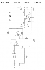
Edit: this is the patent: US5408533A - Motional feedback speaker system with radially polarized magnet and underhung voice-coil
- Google Patents
Jan
Edit: this is the patent: US5408533A - Motional feedback speaker system with radially polarized magnet and underhung voice-coil
- Google Patents
Jan
Attachments
Last edited:
At the output of bridge current comparison circuit and the voltage across the speaker. Used in the 70s.
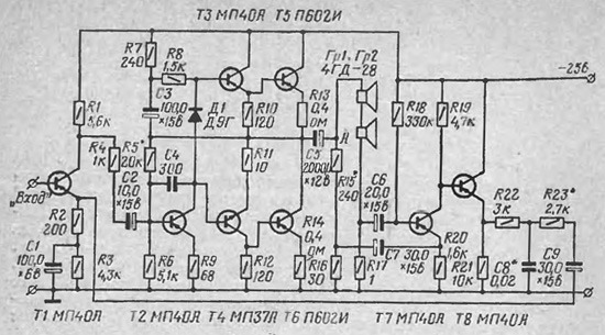
(1973)
(1973)
EMF s.42-44
Журнал <<Радио>> № 9 за 1981 год
s.55
Журнал <<Радио>> № 1 за 1975 год
S.43-45
Стр. 44 журнала <<Радио>> № 3 за 1973 год
Журнал <<Радио>> № 9 за 1981 год
s.55
Журнал <<Радио>> № 1 за 1975 год
S.43-45
Стр. 44 журнала <<Радио>> № 3 за 1973 год
Last edited:
- Home
- Amplifiers
- Solid State
- Where to put feedback loop in amplifier?