I suggest you to clone something more easy
As the Model 310.... as this one we have schematic.
That model you are asking..... i think people has not schematic to provide...so.... you will enter a no exit street... that one have not end...and thread may die if people do not find the schematic to you.
Clone something more interesting...you will have a lot of hits of people interested to clone something alike that.. different...exotic...have Fets...also transistor...something easy to construct.
Well...just a suggestion to you...because start a project into a hard to find schematic will go nowhere i think.
regards,
Carlos
Attachments

Those Fets we can find inside damaged PC supplies
So...there's no complicated thing to find or to buy, nothing hard to find or parts we do not use to have in our junk box.
Needing a better schematic...if no one post the one you want.. come to my mail adress informing yours and i will upload you bigger schematic (bigger data)
panzertoo@yahoo.com
regards,
Carlos
Attachments

Yeah!...of course...maybe someone has that schematic in their home and will cooperate
posting it to us.
But, at least, i have searched and i could find it into the WEB...so.... not so easy to have the model you want.
Please, think about another option...as some clone may be interesting for all of us..forum folks.
A serious work, producing boards layout, constructing, testing and publishing.... a good and decent work about those respectable brands may be very interesting.
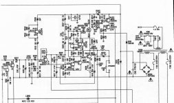
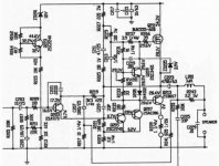
Here is a more simplified schematic...the Model 310
Yes... i hope a forum friend will post the one you want...if not... i am already offering you another option for your analisis.
regards,
Carlos
posting it to us.
But, at least, i have searched and i could find it into the WEB...so.... not so easy to have the model you want.
Please, think about another option...as some clone may be interesting for all of us..forum folks.
A serious work, producing boards layout, constructing, testing and publishing.... a good and decent work about those respectable brands may be very interesting.
Here is a more simplified schematic...the Model 310
Yes... i hope a forum friend will post the one you want...if not... i am already offering you another option for your analisis.
regards,
Carlos
Attachments
Nad 218
I got schematics, saved as bmp or whats its name. Rather large files 11mb per side. Trying to fix a 218 myself.
I got schematics, saved as bmp or whats its name. Rather large files 11mb per side. Trying to fix a 218 myself.
Here you go, for FREE:
http://avforum.no/forum/diy-do-yourself/68146-nad-218-thx-reparasjon.html#post857744
http://avforum.no/forum/diy-do-yourself/68146-nad-218-thx-reparasjon.html#post857744
IsakAlexander said:
Hi IsakAlexander.
Thank you for posting this.
Is the schematic or manual telling what exactly the iddelcurrent has to be by measuring voltage op TP 301 303 302 304???
Iddle current setting with VR301 (VR302) voltage measuring over testpoints TP301 and tp 303 (TP 302 and TP 304)
Does it perhaps tell something to put the finals more in class A ??
Best regards.
Onno
IsakAlexander said:Sorry but those pages are missing from the manual.
Thanks for answewing.
What are you using in your 218 for iddle current ?
Onno

Still after putting in new transistors: MJL3281&complementary I cant get this thing to work.. Fuses dont blow, relays dont turn on and left channel have 1132mV on the speakerterminal.
Anybody have a suggestion to what the h#ll is going on? My guess is somewere on the mainboard, bad soldering, faulty diode or some minor thing.
The right channel only gives very low sound when full input and forced the relay.
Anybody have a suggestion to what the h#ll is going on? My guess is somewere on the mainboard, bad soldering, faulty diode or some minor thing.
The right channel only gives very low sound when full input and forced the relay.
Yes I did measure the drivers and other small ones at the left channel print.
I do belive the fault must be somewhere at the main print, the power section and have read that this model have had rectifier problems. When forcing the relay no sound are outputted, only small dc current. Right channel outputs sound when manually forcing the relay but its very very low even on full input from a cd player.
Could it even be the input section are damaged(op amps), thus making dc on one channel and nothing at the other?
Hi Isak
Did you check on point VR1 there is 82 volts dc !
if not check R 702 and 704 (both 100 ohm).
(on the main (power) print)
second check goes transistor Q 707 open (mute) via
R725 ( 1 megohm) ?
And are both channels not working ? or only one channel ?
Onno
Did you check on point VR1 there is 82 volts dc !
if not check R 702 and 704 (both 100 ohm).
(on the main (power) print)
second check goes transistor Q 707 open (mute) via
R725 ( 1 megohm) ?
And are both channels not working ? or only one channel ?
Onno
I will have to measure it later to see if the voltages are correct, I am new at this so dont want to slip up.
This is what I got:
Between J317 and J321= 145V dc
J319 and J321= 72V dc.
Same value on the other channel, are these the wrong values?
Adjusting the pot`s on either the pre or output print does not change anything.
The resistors R704 and other 100ohm value are all ok.
🙁
Between J317 and J321= 145V dc
J319 and J321= 72V dc.
Same value on the other channel, are these the wrong values?
Adjusting the pot`s on either the pre or output print does not change anything.
The resistors R704 and other 100ohm value are all ok.
🙁
- Status
- Not open for further replies.
- Home
- Amplifiers
- Solid State
- Where to find NAD 218 schematic??