Hi,
With your help i got XR-3324 Manual (Perry helped me).
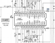
I tried to input(from a mp3 player) using 3(LFIN), 34(RFIN) and 21(GND) but audio quality was not good. then i tried with 11(LTOUT), 26(RTOUT) it worked, but the volume control option is not working. Though i change the volume it doesnt affect.
I have to adjust the volume in my mp3 player.
Can anyone please help me where to connect the left, right and ground, (audio input ) on the PCB.
I have attached Chip Diagram
If you need the Service Manual below is the link
http://chitkuls.webs.com/sony_xr-3324_[ET].pdf
Thanks
Naveen
With your help i got XR-3324 Manual (Perry helped me).
I tried to input(from a mp3 player) using 3(LFIN), 34(RFIN) and 21(GND) but audio quality was not good. then i tried with 11(LTOUT), 26(RTOUT) it worked, but the volume control option is not working. Though i change the volume it doesnt affect.
I have to adjust the volume in my mp3 player.
Can anyone please help me where to connect the left, right and ground, (audio input ) on the PCB.
I have attached Chip Diagram
If you need the Service Manual below is the link
http://chitkuls.webs.com/sony_xr-3324_[ET].pdf
Thanks
Naveen
Attachments
Have you checked the output level of your MP3 player and compared that to the input level spec of the chip you have posted. most likely you dealing with a level mismatch issue where your Mp3 player output is either too high or a mismatched impedance issue..... it appears that you selected the correct input pins to begin with, so this is why I jump to the conclusion that there is a signal level issue.
Another possibility is a DC offset issue, are you capacitor coupling your connection to block any strange DC offsets that may be occurring ??? if I were you I would not be making any direct connections without the use of a DC blocking cap inline with the signal before it enters the HU circuitry....hope this helps some...🙂
Another possibility is a DC offset issue, are you capacitor coupling your connection to block any strange DC offsets that may be occurring ??? if I were you I would not be making any direct connections without the use of a DC blocking cap inline with the signal before it enters the HU circuitry....hope this helps some...🙂
I am using a samsung ypU3 portable mp3 player which has very low output.
Perry: No I dont want to use the cassette player.
Perry: No I dont want to use the cassette player.
On IC501, solder a bridge between pins 1 and 2. Solder another bridge between pins 6 and 7.
Break connections to the tape head at points 9, 10 and 11 on CNP901.
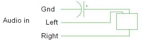
Connect the RCA shield to the line that was connected to pin 10 on CNP901. Insert a 10uF cap between the RCA shield from the mp3 player and the circuit. The value is not critical but the positive terminal has to connect to the op-amp side of the circuit.
Connect the left and right signal lines to the side of C501 and C502 that were originally connected to pins 9 and 11 of CNP901.
You'll have to insert a tape to get the audio to switch to cassette.
Don't expect it to work perfectly. It will likely take a bit of tweaking to get it right.
Break connections to the tape head at points 9, 10 and 11 on CNP901.
Connect the RCA shield to the line that was connected to pin 10 on CNP901. Insert a 10uF cap between the RCA shield from the mp3 player and the circuit. The value is not critical but the positive terminal has to connect to the op-amp side of the circuit.
Connect the left and right signal lines to the side of C501 and C502 that were originally connected to pins 9 and 11 of CNP901.
You'll have to insert a tape to get the audio to switch to cassette.
Don't expect it to work perfectly. It will likely take a bit of tweaking to get it right.
Just Broke the connections from the tape head. and Directly connected the left right channels to pins 1 and 7 and the ground to 4.
Without the capacitor in the shield ground circuit, the MP3 player will have about 4v of DC on it. If it has any exposed metal that's connected to the shield ground or if you use a charger that plugs into the cigarette lighter (power port), it could damage the MP3 player.
Hi Perry,
After i connect a capacitor of 10uf, the voltage has dropped to 2V, and the audio quality is not good. There is some noise, and bass had drastically reduced. Pls help
Thanks
Naveen
After i connect a capacitor of 10uf, the voltage has dropped to 2V, and the audio quality is not good. There is some noise, and bass had drastically reduced. Pls help
Thanks
Naveen
Try connecting a 1k ohm resistor from the MP3-player side of the ground capacitor to the case of the head unit.
- Status
- Not open for further replies.
- Home
- General Interest
- Car Audio
- where to connect audio input on the chip of XR-3324