Hello, I'm currently finishing a new amplifier, but unfortunately this time I'm having a ground loop problem between the two channels.
When I finished the first channel, I didn't have any hum in speaker. It was when I added the second channel that a hum appeared, and I was able to test, as indicated in this document, that this was indeed the problem.
https://hifisonix.com/wp-content/uploads/2019/02/Ground-Loops.pdf
I was able to improve things by modifying my wiring, but a slight hum persists
in the test speakers.
I'd like to add this Hum Breaking Resistor (HBR) if possible, but I admit I'm not sure where to place it.
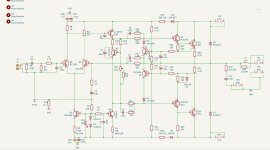
Here is the amplifier schematic:

When I finished the first channel, I didn't have any hum in speaker. It was when I added the second channel that a hum appeared, and I was able to test, as indicated in this document, that this was indeed the problem.
https://hifisonix.com/wp-content/uploads/2019/02/Ground-Loops.pdf
I was able to improve things by modifying my wiring, but a slight hum persists
in the test speakers.
I'd like to add this Hum Breaking Resistor (HBR) if possible, but I admit I'm not sure where to place it.
Here is the amplifier schematic:
check this recent thread : https://www.diyaudio.com/community/threads/l20-5-finished-amp-with-hum.425750/#post-7970465
post some detailed and annotated pictures of the current amp wiring / layout, as HBR may not be required.
post some detailed and annotated pictures of the current amp wiring / layout, as HBR may not be required.
Yes of course there is a chassis connection to earth and the gnd psu its a safety obligation. The psu is a symetrical supply with one toroidal transformer and two diode bridge.
+1Also post the power supply schematic.
I knew this but I'm a mind reader, others take the longer path and need to askYes of course there is a chassis connection to earth and the gnd psu its a safety obligation.
Did you confirm that it's mains 50/60Hz hum or rectified 100/120Hz hum/buzz (on my lunch break so no mind reading...)
Yes of course there is a chassis connection to earth and the gnd psu its a safety obligation. The psu is a symetrical supply with one toroidal transformer and two diode bridge.
Is there a connection between the chassis and the audio circuit common?
I think it is 120hz hum but i Will check it tomorrow in the evening. There one point and only one between the chassis and the gnd star ground of the psu.
Your schematic remembers me about a Nap Amp.....🙂
I had a small problem with the offset of my FH9 XRK Mod amp, but with help we found a solution. One Starpoint, but also connected to the ground of the Input and the problem was solved. I think a groundlift resistor helps against the hum...
Pictures and reading here...post 33, wiring by bonsai, pdf. Post 34 my solution...
Greets
Peter
Attachments
Last edited:

Hello, I have noticed in several amplifiers, the presence of a resistor going to earth, usually 10R that stays in series with the input signal. I still can not understand why he was there.
If anyone can clarify me, I'm very grateful.

If anyone can clarify me, I'm very grateful.
- liustake
- Replies: 42
- Forum: Solid State
I think so..i call it Groundlift. Diffcult for me, i have to learn....clean ground, i call signal ground, dirty ground i call powerground..but it is the same.
The 10 ohm resistor splits clean ground from dirty ground.
R10 is my groundlifter...yep
This is a too broad statement that is not always true depending on local regulation, hardware configuration and voltages involved.Yes of course there is a chassis connection to earth and the gnd psu its a safety obligation.
Yes of course there is a chassis connection to earth and the gnd psu its a safety obligation. The psu is a symetrical supply with one toroidal transformer and two diode bridge.
Of course ... but do you have signal connected to chassis earth?
And where do you have your spkr -ve wire going to?
I had overseen, that you always know the pdf of Hifisonix, about ground loops. Let me ask how you connect ground and earth together ?
I use a loopbreaker https://sound-au.com/earthing.htm
Another way was to use an 10 Ohm resistor (with paralleld capacitor), but with the diodes in the recitifer is the better solution, more safety.
The chinese spaker protections have paralleld connections for the speaker minus . Sometimes it is better to use one bigger wire from starpoint and split behind the speaker protection....(if you use such a protection).
Greets
Peter
Attachments

Last edited:
Tying signal ground to power ground through a resistor near the input seems like a common practice.
But I have another question: I’ve seen designs where the ground reference in the feedback is tied to signal ground. That makes me a bit uneasy, since it could potentially put DC across the speakers if the two ground deviate too much due to something funky being plugged in at the input.
What’s the smart people’s take on that?
I use D. Self system as in his book on amplifiers. Already mentioned here: https://www.diyaudio.com/community/...nding-methods-and-designs.270403/post-4240392
I use D. Self system
why do members keep refering to this?
self's diagram shows only ONE amplifier
problems start when you build a typical STEREO with TWO amplifiers
I used it in the 2 boxes for my active speakers. One box for left, one for right, 4x LM3886 in each box. No hum.
There are 4 cinch inputs isolated from the chassis. All 4 input cinch connectors have their shell terminal connected together on a pcb. At that point the cinch connectors are isolated from the chassis. That common "input GND" is connected to the chassis at the same point as the mains earth input.
From that pcb there is a little coax that goes to each LM3886 board that has a local GND plane. The shield of the coax is connected to the "input GND" of the cinch board and at the LM3886 board GND plane. On the LM3886 board this GND plane is used for the feedback, input filters and LM3886 GND pin and it is connected to the star point of the psu. Each LM3886 board also has a V+, GND, V- connection to the psu but this GND is only used for the bypass capacitors. The GND of the speakers goes from the speaker terminal directly to the star point.
One box for left, one for right
you seem to be describing a "mono-block" setup, with separate psu's in each box.
i assume that the OP's setup, have the L/R amps in one enclosure with one common psu.
I’ve seen designs where the ground reference in the feedback is tied to signal ground. That makes me a bit uneasy, since it could potentially put DC across the speakers if the two ground deviate too much due to something funky being plugged in at the input.
What is the alternative?
- Home
- Amplifiers
- Solid State
- Where should i put the hum breaking resistor?