Hi this is my first post.
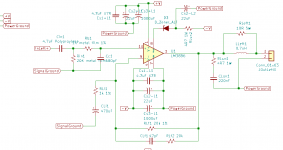
I'm tinkering with an LM3886 circuit that I'm building in my spare time, mostly following the design from a website and partially following the reference diagram from the datasheet.
One thing that's confusing me 😕 is where does the Signal Ground come from?
Does the Signal Ground come from the amp PSU or from the equipment that is providing the audio source waveform (iPod, phone, computer etc)?
The website I'm following as the basis of my build has it coming from the amp PSU.
If it's really supposed to be from the amp PSU, how does the circuit complete itself (conventional current flow) with respects to the audio source equipment, if there doesn't appear to be a path back to the computer? (current flows from the computer into pin 10 of the LM3886 and then flows out via Signal Ground on the amp back into the house wiring?)
Thanks
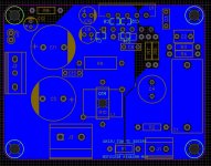
Attachments
Last edited by a moderator:
You've hit on one of the biggest challenges in audio - managing grounds. With single-ended connections its a circle that cannot be squared.
Signal ground is the ground of the signal source - meaning the iPod's 3.5mm jack common connection. But it can't really be at a substantially different potential to the ground at the PSU so normally there is a wire connecting the two. With a battery powered device like an iPod there's no issue but when the source has a connection (even via parasitic capacitance) back to the house wiring then its impossible to stop noise current flowing in the connecting wire I just mentioned.
Btw pin10 of the LM3886 doesn't accept much AC current at all, its a relatively high impedance input. It does need DC bias current though of upto 1uA.
Last edited:
Thanks for your reply.
Is there any danger that the amp PSU's "ground" is floating relative to the source equipment's ground when it gets connected at the amp input?
i.e. What's there to guarantee that the PSU's ground has a potential difference of 0V with respect to the computer's signal ground from the input connector?
Is it really safe to connect the source device's audio connector ground to the amp's PSU's ground? Won't I blow out my computer's audio codec chip that way if there was, say, a 50V potential between them? (I'm not intentionally doing or planning to do this, just thinking out loud, in order to understand)
Further, I'm not sure if the picture in my first post was visible (it isn't for me), but there are Signal Ground and Power Ground defined, and the circuit design I'm following ( at A Complete Guide to Design and Build a Hi-Fi LM3886 Amplifier - Circuit Basics) has multiple hardware connections for ground at the power supply board where the speaker ground, amp power ground, signal ground all join. I've seen pictures on this forum of other people's project and there don't appear to be always be such explicit and specific ground star configurations. Is it enough to have +V, GND, -V going from the PSU board to each channel's LM3886 board, where the grounds are made into star configurations on those boards themselves?
The answer to your 'i.e.' question is the wire I mentioned in post #2. That wire joins the source GND to the amp's PSU GND.
As regards your second 'safety' question I believe its safe yes as they are both isolated from mains (L,N) and likely very close to earth potential. If there were (by means of leakage currents into the source component) a 50V potential difference then that voltage difference would quickly be reduced to near zero by connecting the two with a wire as leakage currents are of the order of 10s or perhaps 100s of uA.
Based on my own experience with amps, I'd not join the PSU and signal grounds together at the power supply, rather as close to the input RCAs as possible. The main thing you want to avoid is having common-mode currents (aka leakage currents) imposing a voltage in series with your source component. Normally that's a recipe for poor SQ as the leakage currents are usually predominantly above the audio band and will intermodulate with the audio leading to a subjective loss of dynamics.
Hi this is my first post.
I'm tinkering with an LM3886 circuit that I'm building in my spare time, mostly following the design from a website and partially following the reference diagram from the datasheet.
One thing that's confusing me 😕 is where does the Signal Ground come from?
Does the Signal Ground come from the amp PSU or from the equipment that is providing the audio source waveform (iPod, phone, computer etc)?
The website I'm following as the basis of my build has it coming from the amp PSU.
If it's really supposed to be from the amp PSU, how does the circuit complete itself (conventional current flow) with respects to the audio source equipment, if there doesn't appear to be a path back to the computer? (current flows from the computer into pin 10 of the LM3886 and then flows out via Signal Ground on the amp back into the house wiring?)
Thanks
I think you are overcomplicating the issue.
First, amplifier, and LM3886 is no exception, is designed to amplify what is presented on its input connector, that is between the live pin and the ground of that connector. That is its ground. This ground must be connected to the power supply ground. If it is symmetrical power supply, then the center, if it is powered by asymmetrical (with cap on output), then negative of two power supply wires.
Signal source is irrelevant, power amp is slave, it amplifies whatever is presented to its input. If your signal source is connected with very long cable and it brings hum, amp does not care, it will amplify music with the hum too. For the amp all is just signal.
Do not mix grounds, there is only one ground.
My PSU is symmetric, so I have a toroid with 2 secondaries and +39V, "0V" and -39V output from my PSU with no load.
Earth connector from the mains plug is not connected, and I'd use that for grounding the metal case once I have one.
If:
A = earth pin of the UK mains cable for the amp
B = 0V from my amp PSU after the filter caps
C = GND from the stereo jack connector from my PC
D = 0V or GND from my PC PSU
Would I expect voltages at A, B, C, D to all be equal with each other if I used a multimeter, and if not, are you saying it doesn't matter?
My intention then is to hook the shield of the RCA input connector (jack on PC, RCA on amp) to the 0V on my amp PSU.
I am not sure how to upload images on this forum to illustrate what I mean, but do you envisage any problems if I connected the RCA shield terminal (which is also connected to the PC ground) like that to the amp 0v?
Thanks 🙂
Voltages cannot just be equal, they are always relative to a reference node.
Choose a reference node (connect the black meter lead there).
Then measure the nodes in question to see if they are at the same (0V),
or at different potentials, as the reference node.
But your question is really how to design the grounding system of an audio component.
http://hifisonix.com/wordpress/wp-content/uploads/2019/02/Ground-Loops.pdf
http://hifisonix.com/wordpress/wp-c...4/ilimzns-Excellent-Posts-on-Ground-Loops.pdf
Last edited:
My PSU is symmetric, so I have a toroid with 2 secondaries and +39V, "0V" and -39V output from my PSU with no load.
Earth connector from the mains plug is not connected, and I'd use that for grounding the metal case once I have one.
If:
A = earth pin of the UK mains cable for the amp
B = 0V from my amp PSU after the filter caps
C = GND from the stereo jack connector from my PC
D = 0V or GND from my PC PSU
Would I expect voltages at A, B, C, D to all be equal with each other if I used a multimeter, and if not, are you saying it doesn't matter?
My intention then is to hook the shield of the RCA input connector (jack on PC, RCA on amp) to the 0V on my amp PSU.
I am not sure how to upload images on this forum to illustrate what I mean, but do you envisage any problems if I connected the RCA shield terminal (which is also connected to the PC ground) like that to the amp 0v?
Thanks 🙂
you are more confused than ever...
I already answered your question. Yet you ask it again in other form. Ground of the input is identical to the center, zero, of the power supply, because they are connected.
Forget A earth pin of UK cable...that's not your ground. That's protection when you mess up.
...
Further, I'm not sure if the picture in my first post was visible (it isn't for me), but there are Signal Ground and Power Ground defined, and the circuit design I'm following ( at A Complete Guide to Design and Build a Hi-Fi LM3886 Amplifier - Circuit Basics) has multiple hardware connections for ground at the power supply board where the speaker ground, amp power ground, signal ground all join. I've seen pictures on this forum of other people's project and there don't appear to be always be such explicit and specific ground star configurations. Is it enough to have +V, GND, -V going from the PSU board to each channel's LM3886 board, where the grounds are made into star configurations on those boards themselves?
Hi
relax😉
Read this pages at this link again (the pictures are very good) and keep in mind what the other members wrote: it is existing just one ground!
chris
tomchr has posted an excellent tutorial on optimising the LM3886 which you should read to understand how that specific chip works and how to properly route the signal return and speaker return.
The word ground is itself a misnomer, it is a purely theoretical concept that has no basis in built circuits, and is useful only in understanding theoretical ones. It is better to think of them as current returns, and then overlay parasitic components of real-world connecting wires and tracks.
Basically the input signal current flows between the bottom of the input stage CCS and the base of the input side diff pair. The output signal is sampled through the other diff pair transistor, and the same CCS junction. It is critical to keep inductance between these two currents to an absolute minimum for the lowest possible distortion, and this basically means to keep them as close to each other and to the input pair.
Obviously this means that external grounding is not a great idea (for any amplifier) as all wires have significant inductance. A ground plane is one solution, but it is far from the only one. This also means that things like isolating power and signal grounds is counterproductive to sound quality and should only be used in special circumstances. Most amplifiers have suboptimal grounding arrangements, usually resorted to because of other considerations (noise, hum, PCB cost and so on) and should not be taken as best practices.
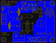
This is the scheme I'm using for my LM3886 boards. It's two ground pours joined either by a "hum-breaker" resistor (R1 - 10ohm) or a solder blob on the bottom. The right side pour is the signal ground. The left side is the power ground. The power ground joins the main system ground at the power supply input on the left. For reference, J1 is the audio input (it's ground connection on the left), J3 is the speaker output. I'm just showing the bottom side of the board here.
Attachments
Can you elaborate on that? Are you talking about the LM3886 ground pin (pin 7)? Tom Christiansen has said it doesn't matter where this is connected, as it's really only relevant when the amp is muted. Taming the LM3886 Chip Amplifier: Grounding – NeurochromeThe chip pin connected to the dirty ground plane in #12 is not the best possible way to do it.
That's unusual, I quite clearly remember an explanation of all the current sources (shown symbolically in the schematic) being referred to that specific ground. I'll see if I can dig up something. I also need to check what happens if the GND pin is disconnected in a running amplifier (which should theoretically be okay if Tom's explanation is the correct one).
I'm pretty sure the muting current is not the only current flowing through that pin, which is what Tom seems to be saying.
I'm pretty sure the muting current is not the only current flowing through that pin, which is what Tom seems to be saying.
Out of curiosity, where would you connect the ground pin? I assume you'd go to the signal ground instead? This is interesting to me, as I'm thinking about the grounding scheme at the moment. Thanks.
My preferred location is close to the junction between speaker return and power supply common, but routed to avoid the local decoupling current. I don't know if that makes sense, so here's a pic. This is not what I finally ended up doing, but I can't locate those files. The planes are enclosed in dotted lines for easy reading.
Besides there's plenty of stuff about pin 7 if you dig deep. The muting is definitely not the only current through the pin, there's quite a lot of functionality, all of which is not revealed by National/TI. Protection features are definitely a part of it as well, as is the tail currents for all the current sources. You could conceivably make current sources that needed no tail currents, but we won't know that for sure.
Besides there's plenty of stuff about pin 7 if you dig deep. The muting is definitely not the only current through the pin, there's quite a lot of functionality, all of which is not revealed by National/TI. Protection features are definitely a part of it as well, as is the tail currents for all the current sources. You could conceivably make current sources that needed no tail currents, but we won't know that for sure.
Attachments

Thanks. That's interesting - I've been considering using smaller pours and routing ground connections in my latest version. I was interested in how Tom suggested how the various ground points should be connected for best results, and came up with the attached. I'd be interested in seeing if such a change would be beneficial. It would also allow me to easily route the chip ground down to the speaker ground as you suggest.
Attachments
Good luck 🙂
I still prefer individual spades to terminal blocks - you do get a lot more freedom in routing currents. I also prefer to separate the decoupling common from the speaker return, this is not possible without a midboard connector (and thus ruling out the use of terminal blocks).
I still prefer individual spades to terminal blocks - you do get a lot more freedom in routing currents. I also prefer to separate the decoupling common from the speaker return, this is not possible without a midboard connector (and thus ruling out the use of terminal blocks).
- Home
- Amplifiers
- Chip Amps
- Where does Signal Ground come from? LM3886