> Get a real VTVM (or FET-VM) with a 10-Meg input and an honest-to-gosh needle.
In other words, not a digital meter. My current DMM is an auto-ranging digital unit from Radio Shack, which I bought because I figured the chances of me blowing that up were less. Is there any way I could see this on a scope, or would it not last long enough?
> With resonable assumptions, like driver B+ is lightly dropped from output stage B+
It is.
> If you use one of these new-fangled totem-pole circuits as your driver, you have a problem.
I don't know if it's new-fangled or not, but my driver is an SRPP 6SL7. I think it's time I implemented my CCS loaded ECC99.
Nope, what I built is this:
It sounds pretty good. I'm just trying to make it better 🙂
An externally hosted image should be here but it was not working when we last tested it.
It sounds pretty good. I'm just trying to make it better 🙂
Hi,
Yeah...Don't we all?
It maybe not related to your problem at all but volpots don't like to see DC on their wiper, it could be the source of intermittent faults such as the spitting you hear.
If you have a 0.47µF handy and a 470K resistor try putting it behind the pot; cap in series, R as gridleak.
Hope this helps,😉
It sounds pretty good. I'm just trying to make it better
Yeah...Don't we all?
It maybe not related to your problem at all but volpots don't like to see DC on their wiper, it could be the source of intermittent faults such as the spitting you hear.
If you have a 0.47µF handy and a 470K resistor try putting it behind the pot; cap in series, R as gridleak.
Hope this helps,😉
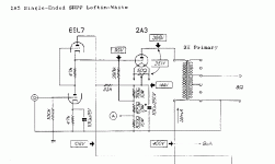
Oh... I don't have that input pot, sorry I didn't mention that. I just linked directly to the schematic on the Angela website instead of drawing my own. I have a 100K fixed-value grid-leak. My linestage is a passive autoformer-based unit.
Hi,
Now I remember, you're the lucky guy with the Davis Slagle volctrl...
Oh, well...The problem may well be the quality of the cap you're using as you suggested.
After all it does couple AC signal back into the cathode but I'm guessing.
I don't know wether you're familiar with the Black Gate caps but if money was no object that what I'd use.
Assuming the amp sounded and measured fine without it, I wonder what else it could be...
Cheers,😉
I just linked directly to the schematic on the Angela website instead of drawing my own. I have a 100K fixed-value grid-leak. My linestage is a passive autoformer-based unit.
Now I remember, you're the lucky guy with the Davis Slagle volctrl...
Oh, well...The problem may well be the quality of the cap you're using as you suggested.
After all it does couple AC signal back into the cathode but I'm guessing.
I don't know wether you're familiar with the Black Gate caps but if money was no object that what I'd use.
Assuming the amp sounded and measured fine without it, I wonder what else it could be...
Cheers,😉
Well, the other thing I changed is to add teh current regulated DC filament supplies on the 2A3s. I used individual Schottkys though, so I don't think it's RF noise. At least, I hope not. I still need to add the 10uF cap after the LT1085 that the datasheet says "is needed for stability", so maybe that might be causing it. But would the music signal modulate the demands on the filament supply? Anyway, I plan to do that the next time I get under the hood, and add common mode chokes to the filaments too.... if it's RF, those might help as well.
Hi,
I am not saying this IS the cause of what you're experiencing but it could be.
Don't forget you're dealing with a DHT triode.
Since your anode to cathode bypass couples PS noise to the cathode / heater it may well be that any noise left on the heater supply is in the loop as well showing up on the scope.
It wouldn't come as a surprise that the unbypassed current reg. is indeed the culprit.
Cheers,😉
But would the music signal modulate the demands on the filament supply? Anyway, I plan to do that the next time I get under the hood, and add common mode chokes to the filaments too.... if it's RF, those might help as well.
I am not saying this IS the cause of what you're experiencing but it could be.
Don't forget you're dealing with a DHT triode.
Since your anode to cathode bypass couples PS noise to the cathode / heater it may well be that any noise left on the heater supply is in the loop as well showing up on the scope.
It wouldn't come as a surprise that the unbypassed current reg. is indeed the culprit.
Cheers,😉
OK, I did something bad last night. One of my channels is now buzzing. Not too loud, but definitely louder than the other channel. It goes completely quiet when I short the input though, which is strange (to me). When connected to the linestage with the selector switch set to the CD player (which was turned on), it buzzes. This is different from removing the interconnect, which makes it buzz/hum much more (which is expected). I tried swapping interconnects, tubes, linestage channels, and the buzz didn't move.
I can think of two things that might have happened:
* I had a marginal solder joint which I knocked loose while poking around under the hood last night.
* At one point I was messing with the scope on the heater circuit with the amp powered up (stupid, I know), and I had a spark that left a mini-crater on an alligator clip. So.... maybe that damaged something? The regulator? Diodes? Cap?
Another weird thing I noticed was that the hum went up a *lot* when I hooked up the scope's probe across the filament pins. Is this a ground loop through the scope? The ground on the probe shouldn't be directly connected to safety earth, should it? That doesn't make sense, because then you can only measure waveforms against earth, you'll never be able to measure between two points in the circuit. Or am I thinking in a multimeter way here, and a scope should always be used with a reference to earth, and the way to measure voltages between different points is to use 2 probes?
Anyway.... I'll try re-flowing the solder joints this evening. Is there some way of narrowing this down? With a regulated DC filament supply, there are quite a few solder joints in there 🙂
Thanks,
Saurav
to narrow down the source of your hum
try clipping the wire between the driver (after the dc-blocking cap) and the power stagesto decouple the stages.
then administer your scope to each of the driver scope sections
.. which reminds me, that's somethng i need to do to my SE 6sn7-6bq5 amp too (separate post forthcoming)
.V.😉
try clipping the wire between the driver (after the dc-blocking cap) and the power stagesto decouple the stages.
then administer your scope to each of the driver scope sections
.. which reminds me, that's somethng i need to do to my SE 6sn7-6bq5 amp too (separate post forthcoming)
.V.😉
That's a good idea. I was reading through some other stuff and realized that I could have bent a pot's terminal to touch the chassis, or something like that - that could probably cause this too.
Well, I think it was mostly my CD-ROM drive. The darn switching power supply in that turned its analog output into a picket fence, and I guess one of my channels is more sensitive to that high frequency noise. I put my older CD player back in, and everything's happy. I did re-flow all solder joints on that input tube just for good measure. Also added the bypass caps for the regulator ICs. Things seem better now. I also re-did the grounding inside the amp, moving the chassis connection to the front of the amp near the inputs. That reduced the amount of HF hash in the output significantly.
So now I need to find an inexpensive CD player/transport that has a digital output (mine doesn't), and doesn't produce picket fences on its output.
So now I need to find an inexpensive CD player/transport that has a digital output (mine doesn't), and doesn't produce picket fences on its output.
- Status
- Not open for further replies.
- Home
- Amplifiers
- Tubes / Valves
- When using a DC filament supply on a DHT...