Looks like this particular build has an issue - looks like there's a leak.
Unfortunately I wasn't there when they were sealing up this particular TH build to ensure all that there were no gaps between the internal panels and the side panel. Hopefully this leak is around the driver. Last time I saw this type of impedance curve, the leak was caused by the driver being slightly off-center of the hole in the baffle.
BTW, this is an B&C 18TBX in what's supposed to be a 33 Hz TH. I'm a bit concerned that all the impedance peaks seem to be shifted upwards a bit, as are some of the peaks in the FR, and the first impedance minimum is actually occurring at 35 Hz. Time to recheck that path length and horn layout. This is also the first build where I tried to incorporate cone compensation into the design by decreasing CSA at S2, so that may have something to do with it too.
Attachments

Looks almost like the TH18
It does a bit 🙂.
I'll be taking a closer look at it next week, to see if the location of the leak can be identified. Once that's sorted, hopefully we'll get a bit more 40 Hz out of it.
Yeah over 17 cubic feet Id expect a lil more low end
Let's see what it does after you find the leak. Hopefully it's an easy fix
Let's see what it does after you find the leak. Hopefully it's an easy fix
Yeah over 17 cubic feet Id expect a lil more low end
Let's see what it does after you find the leak. Hopefully it's an easy fix
With an Fb of (hopefully) 33 Hz, I can EQ up the low end down to there if needed, and enjoy the high efficiency of the design at higher frequencies. It's destined for club use, so portability is a bit less of an issue 🙂.
I spent some time on the horn today to see if I can address the leak.
I found two things wrong with the build, one minor, one major:
1. Screws of two different lengths used to screw in the driver. And only the longer screws were actually biting into the wood, doh. I replaced all of the screws with new ones of equal length.
2. The driver baffle is made of two different pieces of wood, bonded together. Done right, and the driver fits perfectly over the hole leading into S2. It wasn't done right. It looks like the inside panel shifted slightly during construction, which means that the resulting flange is too wide on one side and too narrow on the other. Hmm. Finding a fix for that is going to be interesting.
In the interim, I put some weather-stripping tape around the flange in the hopes of blocking any leaks that might be there and screwed back in the driver.
The impedance curve (see below) suggests that (1) the leak has been blocked a little, and (2) it's still there. The first minimum impedance point dropped from 34.9 Hz to 32.9 Hz, but the lowest peak is still too high. Grrr. However, note that HornResp predicts that this minimum will occur at 32.8 Hz! If the leak actually IS at the flange, then once I solve that it's possible that Fb will drop below the HornResp prediction.
Attachments
...and the leak is still there, but it's impact has been reduced. F3 is now down to 36.5 Hz instead of 42 Hz.
HornResp predicts F3 around 33 Hz. I wonder how close I'll get if I manage to completely fix the leak?
I need to come up with a way to sort out the issue with the flange...
HornResp predicts F3 around 33 Hz. I wonder how close I'll get if I manage to completely fix the leak?
I need to come up with a way to sort out the issue with the flange...
Attachments
is there a standard gasket which would fix the leaks? silicon RTV if used to mount can hold "too well" - can you get to it with duct tape?
is there a standard gasket which would fix the leaks? silicon RTV if used to mount can hold "too well" - can you get to it with duct tape?
While discussing/arguing with SWMBO about the issue, I think I may have come up with a possible solution.
I'm going to try a gasket cut out from matt board, the outer dimension being the outer dimension of the driver and the inner dimension being slightly smaller then the mounting hole, and I will try using that between the driver and the baffle.
If this works as planned, then my cousin can use his epoxy/filler stuff to extend the flange to meet the inner edge of the gasket so it can be subsequently removed.
I might just get 33 Hz (and maybe even a little below that) out of this TH yet...
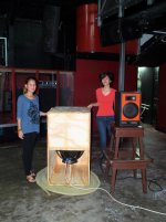
BTW - when I crank up the power into this TH (from an iNuke 6000DSP), the box actually starts moving across the floor and sounding a bit gross due to panel flex, and this is way before the driver reaches anywhere near its excursion limits. Once I get that leak sorted out, I'll have to look at how that bottom panel is braced. Obviously it needs a bit more than the center brace that's currently in place.
It looks like the inside panel shifted slightly during construction, which means that the resulting flange is too wide on one side and too narrow on the other.
I confirmed that there is a leak around the driver, and it's likely caused by the too-short flange. I basically ran a test tone through the sub at the frequency where the FR graph dips. Noisy bursts of air were coming from not, not two, but three of the bolt holes for the driver. Goddammit... .
My brother wanted a demo, so I put some tape over the leaky bolt holes and hooked up the sub and one of my Blastorama tops, x-over at 150 Hz, with an iNuke 6000 DSP providing the power and filtering. Even at that high filter frequency, the Blastorama top was giving out long before the sub. My brother and his workers were impressed. Just wait until the leak is sorted out and the bracing at the mouth is completed, muhahaha... 😀
Persiverence 😉 Following 🙂
Here's the gasket I'm going to try to address the leak around the driver - I want my 32 Hz! 🙂.
Note: the BTX100 specs suggest a 422mm cutout is required, but I think that's for when the driver is mounted *through* the baffle. When mounted facing into the hole, 422mm may actually be a little too wide. A slight miscalculation and well, you end up what happened to this build. So, I've made this gasket with a 418mm internal diameter. I think even going down to 416mm should be safe, because there's no way the surround is going to touch - the BTX100 doesn't have enough excursion capability to achieve that.
Hopefully that's the only leak - it will NOT be funny if there's another one along the folds somewhere...!
Attachments

its your god-given right to have 32Hz !!!! - could you take a plastic syringe with a narrow tip and squirt some PVA into suspect areas?
its your god-given right to have 32Hz !!!! - could you take a plastic syringe with a narrow tip and squirt some PVA into suspect areas?
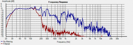
I'll just put this measurement up here for now - this is the response with the temporary flange fix and some weather-stripping tape added for good measure...������
Attachments
I'm going to try a gasket cut out from matt board, the outer dimension being the outer dimension of the driver and the inner dimension being slightly smaller then the mounting hole, and I will try using that between the driver and the baffle.
Looks like the temporary gasket idea worked. Here's what the response looks like now, compared to the HornResp sim (first image), and what it looks like now compared to the initial FR.
I'm going to call this a success 🙂. I expect even better improvement once a more permanent solution for the too-narrow flange is put into place. Looks like I'm going to get my 32 Hz after all 🙂
Attachments
I'm going to call this a success 🙂.
Hi Brian,
A very interesting exercise. It clearly highlights the significant effect that panel resonances and air leakages can have on overall response. Well done.
Kind regards,
David
Hi Brian,
A very interesting exercise. It clearly highlights the significant effect that panel resonances and air leakages can have on overall response. Well done.
Kind regards,
David
Thanks David. The box as-is still needs a bit more bracing (to stiffen the bottom panel), but it's sounding pretty good as it is, basically almost at that point that further improvements would make only slight differences that will likely be unnoticeable to everything but good measuring equipment. I put it through a power test tonight for about an hour and a half and it survived intact, so it's time to build a few more - I told my brother that he needs four 🙂.
The build also proves the validity of the spreadsheet that I used to sim the physical layout and derive the corresponding HornResp parameters - another good thing. Now I can feel comfortable spending more time on the spreadsheet to include some other features I've been thinking about.
Attachments
- Status
- Not open for further replies.
- Home
- Loudspeakers
- Subwoofers
- When things don't go quite as planned...