Hi again. I know I'm a pain 😛
I have been reading about battery powered amplifiers and have wondered when does AC ripple start to become a non issue with B+ in high voltage PS's...
If people claim a much 'stronger' and punchier amplifier sound aswell as a cleaner sound in midrange, why hold back on the caps when a high voltage PS is involved, if the technology is here that can (barely) do these risky things?
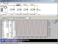
Here I have posted a shot of PSUD showing us Capacitor 2 as you can easily see plenty of ripple and even this is straight after the choke obviously taking it's ripple to earth and leaving a majority amount of DC available for the next 'stage'.
My question is, when is B+ really DC? maybe the final line in getting the best from a Valve amplifier is having a clean power supply of plentiful DC?
They ARE mean't to be DC devices! not AC, maybe ripple disturbs not only the waveform before it's injected into the tube, but maybe the damaging effects are amplified to a greater degree where it matters inside the valve?
We are trying to amplify a weak signal and turn it into a more powerful one. Maybe we are amplifying the effects of AC before it's turned into a larger signal but take nothing against it because the AC isn't evident in the amplified signal?
Try being a weak rubber ducky sometime against a boat (AC)which makes no noise because it's too far away, but the duck (small noise) get's drowned because of it's effects upon the electrons around it? err water...
The revision has called for drastic measures to see if I can do anything about it within a space restriction and reason.
Cheers. Yes I know I'm nutz 🙂
I have been reading about battery powered amplifiers and have wondered when does AC ripple start to become a non issue with B+ in high voltage PS's...
If people claim a much 'stronger' and punchier amplifier sound aswell as a cleaner sound in midrange, why hold back on the caps when a high voltage PS is involved, if the technology is here that can (barely) do these risky things?
Here I have posted a shot of PSUD showing us Capacitor 2 as you can easily see plenty of ripple and even this is straight after the choke obviously taking it's ripple to earth and leaving a majority amount of DC available for the next 'stage'.
My question is, when is B+ really DC? maybe the final line in getting the best from a Valve amplifier is having a clean power supply of plentiful DC?
They ARE mean't to be DC devices! not AC, maybe ripple disturbs not only the waveform before it's injected into the tube, but maybe the damaging effects are amplified to a greater degree where it matters inside the valve?
We are trying to amplify a weak signal and turn it into a more powerful one. Maybe we are amplifying the effects of AC before it's turned into a larger signal but take nothing against it because the AC isn't evident in the amplified signal?
Try being a weak rubber ducky sometime against a boat (AC)which makes no noise because it's too far away, but the duck (small noise) get's drowned because of it's effects upon the electrons around it? err water...
The revision has called for drastic measures to see if I can do anything about it within a space restriction and reason.
Cheers. Yes I know I'm nutz 🙂
Attachments
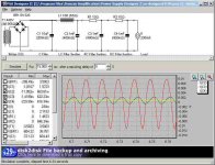
having 5x 100uF caps instead of 3x 1mF capacitors do the same job as each other, but become a much larger issue with space.
It may be better in the long run for 3x 1mF capacitors with the less amount of dielectric and larger amount of metal.
What do you think is better in the long run?
A larger amount of dielectric, does dielectric in numbers matter with drying out?
or a tightly packed lessened dielectric?
Does temperature play a great role in differing results with these two options?
More importantly, I haven't seen any difference in voltage when operating point is in question while varying capacitance as wild as this between ither options 3x 1mF, 5x 100uF when compared with the 'standard' 3x 100uF designs.
Attachments
You know that you are looking at the ripple CURRENT in the filter caps and NOT the power supply output voltage don't you? Its the power supply output voltage that we are trying to turn into DC ( look at the V(C6). In order for a cap to smooth out the ripple in a power supply there will be a lot of ripple current as the cap charges and discharges. That is how the cap does the filtering, by suppling current in the valleys and charging on the peaks.
Later BZ
Later BZ
I don't see how PS voltage alone is what makes DC, afterall AC is Alternating current and DC is Dead/Direct current.
Sure current varies voltage, that's what AC is, but DC doesn't vary current or voltage in a battery.
okay, I see now:
So then whatever the capacitor cannot store at one peak is given onto the next device in the chain, namely the next capacitor or the amplifier components.
Sure current varies voltage, that's what AC is, but DC doesn't vary current or voltage in a battery.
okay, I see now:
That is how the cap does the filtering, by suppling current in the valleys and charging on the peaks.
So then whatever the capacitor cannot store at one peak is given onto the next device in the chain, namely the next capacitor or the amplifier components.
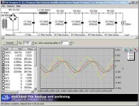
The output of the power supply is Current at a Voltage, correct? Yes AC current is what charges the cap of the power supply BUT clean DC Voltage is what we want to supply to the load. The resistance/conductance of the load determines the amount of current that the power supply delivers.
What you are looking at is the charging current and discharge current of the filter caps and I would expect to see ripple there. That's how the caps do the filtering, by suppling current as the voltage drops and apsorbing current as the voltage rises when the AC sign wave peaks.
BZ
What you are looking at is the charging current and discharge current of the filter caps and I would expect to see ripple there. That's how the caps do the filtering, by suppling current as the voltage drops and apsorbing current as the voltage rises when the AC sign wave peaks.
BZ
I have been reading about battery powered amplifiers and have wondered when does AC ripple start to become a non issue with B+ in high voltage PS's...
With a SS rectifier bridge, you should use a much bigger first filter cap. Watch the surge current ratings of the diodes (and the caps you use!), but possibly 100uF or so. This has massive ripple reduction.
A simple 100uF-10H-470uF would have pretty awesome ripple reduction. Of course realise that you can never get it totally to zero, it is an asymptote function. But if you look at the voltage domain you will see insignificant ripple.
Also realise that in PP, most ripple is cancelled in the output transformer, because it is opposite phase in each valve. The Leak TL12 Point One used just 8uF-10H-8uF and they were pretty silent.
I don't think you will need more than 100-10-470 for a silent amplifier. Your design is overcomplicated, which may result in sonic degradation and unreliability.

As an aside, I used a 1.2H choke into a 560uF cap for a 240mA supply and the amp was dead silent, apart from the choke which buzzes quietly. 😀
- Status
- Not open for further replies.
- Home
- Amplifiers
- Tubes / Valves
- When is capacitance making AC ripple a non-issue in B+ PS's?