Been thinking about this for years 😀
As it's been talked about on here recently, i thought it would be worthwhile exploring.
Including a hole/s etc in a sealed box to help reduce the build of heat caused by the driver.
Seems like a good idea, but. Doing that creates a reflex etc enclosure. The idea though is to not tune it low, or even anywhere near low, so as not to affect the bass. BUT, it will still have a tuning affect higher up !
Arbitarily making a hole/s etc isn't accounting for the tuning effect.
Thoughts ?
If you worked within aperiodic (leaky)box parameters.....mainly the sealed box needs to be too small to start.
I’m thinking odd noises would be the biggest obstacle (whistling,chuffing etc)
Of course I know little of this technically speaking
Bob
I’m thinking odd noises would be the biggest obstacle (whistling,chuffing etc)
Of course I know little of this technically speaking
Bob
Never really worried about heat build up as my stuff is for home use.
Reverse mounting the driver would solve the problem without messing about with holes in the enclosure.
How about looking into water cooling the magnet like they do with cpu's in some hi performance pc's ?
Reverse mounting the driver would solve the problem without messing about with holes in the enclosure.
How about looking into water cooling the magnet like they do with cpu's in some hi performance pc's ?
I actually own tweeters with an aluminum finned heat sink attached to the back plate.
I would have thought it more valuable on larger motors, but I'm not here to judge.
I can't see having a 'hole' in the cabinet as being particularly effective in motor heat reduction, without air flow. Perhaps if the intake hole is right below the motor and the exhaust is right above, you might achieve a natural flue affect, but by the time you start dealing with effective heat dissipation you have thrown off the cabinet tuning. Just my thoughts.
If i'm right on what was the original thread, the purpose of a hole was about reducing DC pressure (mean pressure) to avoid pressure on cone generated by rising temperature. Reverve mounting speaker for closed sub is the way to go. Or, a volt woofers, with reverse magnet/cone.
Then a pin hole would do as Linkwitz suggests, nothing like a port, but then I don't know what this thread is about, I have an idea though 😉
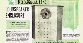
Q: When is a port not a port?
A: When it is a distributed port!
This is brilliant! A small orifice acts like an acoustical resistance now they are paralleled add "special" properties of different patterns and just think of the possibilities.
I once had a 3.6 cubic foot reflex loaded with a Peavey 15 - removable port panel. With a port panel having 43 - 3/8" holes and 10 watts sine input around fb, there was a breeze felt 8 foot away. Port rectification. It moved a lot of air for 10 watts - but an expensive way of having a fan.
A small drilled hole in a closed box will not funtion as a tuned port due to reaching very high velocities and becoming fully turbulent already at a fraction of a watt.
I would not recomend a drilled hole in the box wall. I recomend using a long and very thin pipe. A 1 mm inner diameter steel pipe 30 cm long will have any port like behaviour at extremly low frequencies, but will help equalize the pressure and counteract heat-based pressure buildup (expanding air) inside the closed box without functioning as a lossy leak above 1 Hz or so.
A port as part of a Helmholtz resonator needs to contribute to the function of the resonant system in the intended range of spl and frequencies.
Due to the problem with turbulence and compression I would much prefer a passive radiator with at least 2 x Sd of the driver instead of a normal tube based port.
I once had a 3.6 cubic foot reflex loaded with a Peavey 15 . . . With a port panel having 43 - 3/8" holes
WARNING: Computer free zone!
If anyone wants to experiment with an array of holes (a distributed port) rather than a traditional tuned port, here's some information to get you in the right ball park:
5 holes of 0.5" diameter have an equivalent area of 1 sq inch.
Allow 10 sq inches for each cubic foot of cabinet volume.
e.g. A 2 cu ft enclosure would require 2x10x5 = 100 holes (in a suggested arrangement of 10 rows of 10 holes).
The holes should be spaced 0.75" apart, measured from centre to centre.
It is usual to line the distributed port with a thin, felt cloth to increase the acoustic resistance, but this is another area for experimentation. 😎
This is not an exact science freddi! 🙂
My dimensional details come from the days when enclosures were routinely constructed from 3/4 inch chipboard.
1/2" diameter holes will cater for the normal range of panel thicknesses.
I suspect that thicker panels may introduce more acoustic resistance equivalent to lining the distributed port with felt cloth.
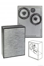
Yes freddi, the first mention of the use of an acoustic resistance unit (ARU).
As you will be aware, Dynaco would later adopt the design shown in Fig.1 in their A50 speaker which was vented, via the ARU, into the bottom half of the cabinet.
The design shown in Fig.3 was adopted in the A10 and A25 speakers which were vented, via the ARU, to the outside of the cabinet.
As you will be aware, Dynaco would later adopt the design shown in Fig.1 in their A50 speaker which was vented, via the ARU, into the bottom half of the cabinet.
The design shown in Fig.3 was adopted in the A10 and A25 speakers which were vented, via the ARU, to the outside of the cabinet.
Attachments

The fact of the half-dozen archetype "suspensions" we all talk about discourages builders (Hafler excepted) from recognizing the utility of hybrid solutions.
Better to ask, "In my application, how can I best manage the power at the rear of the driver?" Not, "Which box tickles my fancy?"
Long pipe to sequester rear wave
B.
Better to ask, "In my application, how can I best manage the power at the rear of the driver?" Not, "Which box tickles my fancy?"
Long pipe to sequester rear wave
B.
Last edited:
hi Galu - here's roughly what I get for a Dynaco A35 type with Seas A26RE4. I goofed and left 2v input from a previous sim
with a 4 ohm speaker.
- 40 some years ago I had 4 of them with Citation 12 amp. Time really goes fast

with a 4 ohm speaker.
- 40 some years ago I had 4 of them with Citation 12 amp. Time really goes fast
Interesting results!
Your impedance plot supports the view that an aperiodic enclosure is more closely related to a sealed enclosure than to a ported enclosure.
The single impedance peak due to cone resonance is visible, but it has been greatly reduced in magnitude (Q) by the action of the ARU.
Although not completely aperiodic (without resonance) the resonant behaviour is greatly reduced which should result in a faster transient response.
- Status
- Not open for further replies.
- Home
- Loudspeakers
- Subwoofers
- When is a Port not a Port ?