Oh BTW, thanks andy_c for the Gilbert article! 😉
Had fun reading it and the math was on a comfortable level.
/Magnus
Had fun reading it and the math was on a comfortable level.
/Magnus
John, here is the promised plot
John,
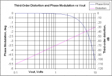
I've taken the equations from Gilbert's paper and extended his example a bit. His example looks at the phase shift at several output levels at a frequency of 1/100 of the gain-bandwidth product. I've changed this a bit. I'm still using 1/100 of the gain-bandwidth product as the test frequency, but I'm plotting the actual phase shift minus the phase shift assuming a linear system. I've called this the phase modulation. I've taken output levels from 0.1 Volt to 10 Volts in 0.1 Volt steps. On the right axis I've plotted the ratio of the third harmonic to the fundamental in dB referenced to the input. Recall that he assumes a distortionless output and computes the distorted input. So I compute the input distortion. I've plotted it against a log voltage scale to show that the distortion is proportional to the amplitude squared per the usual result. This shows that for 1 degree of phase modulation, the third harmonic is not quite 45 dB below the fundamental.
I can provide more info on request, including MathCad and Excel worksheets.
Enjoy.
John,
I've taken the equations from Gilbert's paper and extended his example a bit. His example looks at the phase shift at several output levels at a frequency of 1/100 of the gain-bandwidth product. I've changed this a bit. I'm still using 1/100 of the gain-bandwidth product as the test frequency, but I'm plotting the actual phase shift minus the phase shift assuming a linear system. I've called this the phase modulation. I've taken output levels from 0.1 Volt to 10 Volts in 0.1 Volt steps. On the right axis I've plotted the ratio of the third harmonic to the fundamental in dB referenced to the input. Recall that he assumes a distortionless output and computes the distorted input. So I compute the input distortion. I've plotted it against a log voltage scale to show that the distortion is proportional to the amplitude squared per the usual result. This shows that for 1 degree of phase modulation, the third harmonic is not quite 45 dB below the fundamental.
I can provide more info on request, including MathCad and Excel worksheets.
Enjoy.
Attachments
With the last posts from Swedish Chef and AndyC, can we put this thread to bed now?
The data doesn't get much plainer than this.
The data doesn't get much plainer than this.
Mike Gergen said:The data doesn't get much plainer than this.
I am curious: Is everyone satisfied that:
1)..that NFB is an inherently bad thing?
2)...that 2-tone stimuli provide insight into circuit behaviour that THD analysis cannot?
3)...and that moreover, THD will not detect changes in linearity (or non-linearity thereof) that may be detected by the multi-tone
approach?

Mike Gergen said:..........A bad amp now for example has a delay of 200nS at 1Khz and 250nS at 5khz......
This is incredibly untrue...i am sorry...really..
A closed-loop power amp. cannot have a change in group delay of 50ns between 1khz and 5khz.... 😱
Hi Andy...
...what conclusions have you drawn from these results...?
P.S: This is precisely the sort of dialogue i have been looking for.... 🙂
Cheers!
...what conclusions have you drawn from these results...?
P.S: This is precisely the sort of dialogue i have been looking for.... 🙂
Cheers!
Re: Hi Andy...
Well, if I understood John's previous post correctly, his concern was that the mechanism described by Gilbert that causes a variable phase shift of the fundamental with input level, would somehow "hide" from a conventional harmonic distortion test. The graph shows, using Gilbert's equations, that for 1 degree of phase variation from the linear case, the third harmonic is ~45 dB down from the fundamental. So it isn't hiding at all.
BTW, I forgot to mention in my previous post that the plot was taken with a closed-loop gain of 10, same as Gilbert's example.
mikeks said:...what conclusions have you drawn from these results...?
Well, if I understood John's previous post correctly, his concern was that the mechanism described by Gilbert that causes a variable phase shift of the fundamental with input level, would somehow "hide" from a conventional harmonic distortion test. The graph shows, using Gilbert's equations, that for 1 degree of phase variation from the linear case, the third harmonic is ~45 dB down from the fundamental. So it isn't hiding at all.
BTW, I forgot to mention in my previous post that the plot was taken with a closed-loop gain of 10, same as Gilbert's example.
Re: Re: Hi Andy...
My thoughts precisely.......Cheers.
andy_c said:..............would somehow "hide" from a conventional harmonic distortion test.......it isn't hiding at all..........
My thoughts precisely.......Cheers.
For a -45 DB 3rd harmonic, that translates to a THD of close to .006%. Only some of the better THD meters are going to see this. It isn't that it's hiding, it's just hard to resolve.
Just to clarify, I'm not in the "harmonic distortion describes everything you need to know about distortion" camp, unless the nonlinearity being considered is memroyless.
Consider the Gilbert article again, where the input stage distorts, but the rest of the amp is distortionless. We know that the same mechanism that produces a third harmonic will also produce a 2f1 - f2 term in a simple two-tone test. Now suppose f2 = 20kHz and f1 = 10010 Hz. We get 2f1 - f2 = 20 Hz. There will be a distortion component at 20 Hz in the diff amp collector current. Don't you agree that the transimpedance ratio (from the freq comp) of 20 kHz vs 20 Hz will tend to make this sideband look much larger at the output relative to the carrier than it is in the collector current waveform? See the problem?
Consider the Gilbert article again, where the input stage distorts, but the rest of the amp is distortionless. We know that the same mechanism that produces a third harmonic will also produce a 2f1 - f2 term in a simple two-tone test. Now suppose f2 = 20kHz and f1 = 10010 Hz. We get 2f1 - f2 = 20 Hz. There will be a distortion component at 20 Hz in the diff amp collector current. Don't you agree that the transimpedance ratio (from the freq comp) of 20 kHz vs 20 Hz will tend to make this sideband look much larger at the output relative to the carrier than it is in the collector current waveform? See the problem?
Mike Gergen said:For a -45 DB 3rd harmonic, that translates to a THD of close to .006%. Only some of the better THD meters are going to see this. It isn't that it's hiding, it's just hard to resolve.
40 dB is 1 percent voltage. 46 dB is 0.5 percent voltage.
For a -45 DB 3rd harmonic, that translates to a THD of close to .006%.
What am I not seeing? Or did you slip some zeros?
andy_c said:Don't you agree that the transimpedance ratio (from the freq comp) of 20 kHz vs 20 Hz will tend to make this sideband look much larger at the output relative to the carrier than it is in the collector current waveform? See the problem?
Absolutely....but what relative levels are we looking at here...?
Moreover, this is why single pole compensation is not a good idea, (unless it includes the output stage.....but that's another story.)...
Double-pole...or other similarly derived compesation should take care of this....
I am now working on applying Gilbert to a double-pole comp. model......
OOPs.
I'm trying to do 2 other things a the moment. Andy is right. I goofed with the calculator.
I'm trying to do 2 other things a the moment. Andy is right. I goofed with the calculator.
mikeks said:Absolutely....but what relative levels are we looking at here...?
Moreover, this is why single pole compensation is not a good idea
If we're talking an IC op-amp with very large open-loop gain, and an open-loop pole less than 20 Hz, (extreme I know), there will be 60 dB difference in open-loop gain between 20 Hz and 20 kHz. Pretty darn big.
Yes, the two-pole compensation is looking better all the time, isn't it? But for IC op-amps, you're stuck with single-pole.
andy_c said:
Yes, the two-pole compensation is looking better all the time, isn't it? But for IC op-amps, you're stuck with single-pole.
Which is why externaly compensated op amps are a 'good thing'... 🙂
See:
http://www.st-and.demon.co.uk/Audio/700/700page5.html
"And yes, i am talking of delays below 1uS.
For example, you have a mixture of 1Khz and 5khz. A bad amp now
for example has a delay of 200nS at 1Khz and 250nS at 5khz."
Assuming that this is true. How can it possibly be measured? At 1Khz a 200nS delay is less than 1/2 degree. No way a Thd meter is going to catch this.
No a THD meter will not measure this simply because it is a LINEAR "distortion" and not a non-linear.
First, any decent amp will have negligible phase shift in the audio band. Not that it matters because the crossover will induce 45-180 degrees of phase shift anyway. And the human ear is very insensitive to phase shifts. Otherwise everyday living would be pretty hard...
Andy, great work on the phase distortion issue! 
I knew it would take an RF engineer to sort this out. 😀
/Magnus
I knew it would take an RF engineer to sort this out. 😀
/Magnus
- Status
- Not open for further replies.
- Home
- Amplifiers
- Solid State
- "What's your reasoning?" and not "What's your belief?".