I've been using non balanced passive I/V combined with volume control for some time.
On most levels it sounds great but with certain material and resistor (load) settings something goes wrong (I assuming I run into the issues descibed here http://www.dddac.de/pcm63/DAC_I-V_Resistor.htm
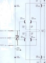
The pic below shows the input stage of a non feedback power amp and my thinking is to feed the balance input directly from I out on a balanced DAC.
I'll put a attenuator with different resistor values between + and - on the input to control volume.
I can't get my head around what actually happens here and hope someone can help shed som light on the issues I will run into?
For example, will each dacs I out convert to V over the r setting in the attenuator and the other dacs output resistance or will I keep I intact and just use the variable R to control the amount of out of phase "summing" to control the current going to the input stage and then get converted to voltage?
I am probably not very clear but looking at the picture might help.
Thx
On most levels it sounds great but with certain material and resistor (load) settings something goes wrong (I assuming I run into the issues descibed here http://www.dddac.de/pcm63/DAC_I-V_Resistor.htm
The pic below shows the input stage of a non feedback power amp and my thinking is to feed the balance input directly from I out on a balanced DAC.
I'll put a attenuator with different resistor values between + and - on the input to control volume.
I can't get my head around what actually happens here and hope someone can help shed som light on the issues I will run into?
For example, will each dacs I out convert to V over the r setting in the attenuator and the other dacs output resistance or will I keep I intact and just use the variable R to control the amount of out of phase "summing" to control the current going to the input stage and then get converted to voltage?
I am probably not very clear but looking at the picture might help.
Thx
Attachments
passive stuff
Essentially what you do (because the input Z of the amp can be disregarded, it is very high), is connecting a resistor across the two Iout's. Assuming you have two complementary Iouts, meaning that if one sources current, the other sinks current, you get a nice voltage across the volume resistor. The current comes out of one DAC output, goes through the vol res, then back into the other DAC output.
The voltage across the vol res acts as a differential input voltage for the amp. So far so good.
But: what if the two Iouts are not equal. Then there is an excess or lack of current, which has to go somewhere or come from somewhere. Something will have to give, and I suspect that one or the other DAC output will distort grossly.
So: better to use two vol resistors, each to ground, but tracking. Although tracking is not critical to sound quality.
Jan Didden
I think that there also could be a problem when the two devices (DAc and poweramp) are not connected to the same ground, but are left floating.
Regards,
Thijs
PS
I interested in designing a small Class A NON NFB solidstate amp myself. Would you mind sharing your circuit?
Regards,
Thijs
PS
I interested in designing a small Class A NON NFB solidstate amp myself. Would you mind sharing your circuit?
There will be 2 PCM1704K sharing the same powersupply per channel where one is inverted.
The power amp and dac share the same ground plane.
Not sure if that means I have two complementary I outs?
Can't use two volume resistors to ground without getting the distortion I referred to above.
tschrama, -sure, nothing you can't find on the web..... http://www.lcaudio.dk/zap.htm there is a tab for diagram that pulls down a pdf file with the details.
passive v/i
Sorry, can't find any reference to "distortion" in your post. Or do you mean the phrase "something goes wrong"?
You really have to give a little bit more info if you expect a usefull answer...
Jan Didden
Sorry, can't find any reference to "distortion" in your post. Or do you mean the phrase "something goes wrong"?
You really have to give a little bit more info if you expect a usefull answer...
Jan Didden
Sorry, -yes it was the reference to somethingoes wrong.
The details of it was in the link on my initial post.
The core of it, from the link above, as follows
Here is the link again
passive i-v distorsion
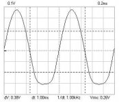
and a picture showing the output signal with a 200ohm load
The details of it was in the link on my initial post.
The core of it, from the link above, as follows
The PCM 63 has protecting diodes in the Output circuits. This could result in heavy distortion / (soft) clipping when the signal goes over the conducting point of the diodes. The maximum current from the PCM 63 is 4mA peak-peak. So the value of the resistor (Ro) should be selected in such a way that the Vout does not exceed this voltage (round 0.7Volt) at max I out.
Here is the link again
passive i-v distorsion
and a picture showing the output signal with a 200ohm load
Attachments
passive i/v
OK, got it. So, do I understand that you have this type of distortion? When you say "things go wrong" what actually happens?
What resistance value do you use? I seem to remember that I have seen values from 100 Ohms downward, which would make sense. Even at 160 Ohms as shown by Douma you are approaching the distortion point, and there really is no need. At 100Ohms, you get some 300mV RMS, just open the volume control a bit further.
Personally I find the resistor i/v very unelegant. It makes the DAC do something that it is specifically designed for NOT to do, ie output voltage. But YMMV.
Jan Didden
I would have 2 pull up resistors before the pot on that schematic maintaining a constant impedance or what you want to call it...to the source...but Heck what do I know
Its less audible then one might think, when it is heard its like a slight fuzziness/harshness added to the sound.
I might hear compression as well but I can not say if that is on the recording or due to the passive I-V
For most levels and source material I can stay below 160 ohms and its fine but on occasion I use up to 500 ohms.
Irrespective of the resistance levels, as you can see on the webpage passive I-V still makes for high distorsion compared to the spec of the dac chip.
I know I could put in an op-amp but I really want to keep amplification stages to an absolut minimum.
I was thinking/hoping that the connection and set up I described would not work as a passive i-v but rather as some form of "linear current control".
From your description I understand it will still be a passive i-v and not really solve what I wanted?
- Status
- Not open for further replies.
- Home
- Source & Line
- Digital Source
- What's this, passive I/V or what?