From time to time I read about the issue of narrowband bandpass filters for typically a midrange driver. The issue should be that the cut off frequencies for the high pass and low pass filters respectively end up too close to each others, and that ringing could possibly be the result.
Can someone please try and explain the theory behind this and how one can test (in measurements and listening) if you have an issue with this.
As far as I remember my filter classes at college (long time ago) I can understand that if the cut of frequencies are close to each others, then you cannot disregard the influence one filter part has on the other in your calculations (specifically for passive filters). It is no longer enough to calculate filter values on the assumption that your source impedance is zero and load impedance is the driver impedance. So you have to design your filter with the interdependencies all the components have on each other.
But if you manage this task and can verify your design with controlled frequency and impedance graphs, are you home then? Or can your design still begin to resonate and misbehave due to some other specific condition?
Can you verify in any way, that you do not have any problems with ringing in a narrowband bandpass filters?
Maybe on a similar topic. Can someone please explain what the loudspeaker company ATC mean with the statement below? In my world it is enough to just shunt the driver with a resistance to make the impedance fall below the voice coil resistance. I understand that the amplifier has to work harder with the lower load impedance, but that this would create a ringing filter with time distortion, that I do not understand.
Statement from the ATC marketing:
The complex motional impedance of a typical two or three way passive loudspeaker system must have a modulus of impedance which varies within defined limits, never falling below the voice coil resistance. A minimum impedance modulus which does fall below the voice coil resistance indicates a ringing filter
in the passive crossover which will cause time domain distortion as well as presenting a difficult load for the driving amplifier.
Looking forward to your comments.
Best Regards, Mats
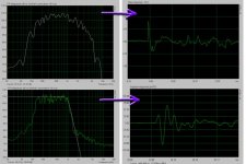
In the end, speaker design is about the summing of bandpass filters. You will have phase shift at every corner of a multiway system. More filters of narrower bandwidth will need sharper corners and generally lead to more phase rotation. The phase rotation can be evaluated as group delay and there are thresholds of audibility that will be surpassed in extreme cases.
As your bandpasses get narrower the ringing will be worse. For example, if I remember correctly a 1/3rd Octave bandpass filter will always have roughly 4 cycles of ringing. Narrower bandpasses will ring longer.
Here was an example of a 12 way speaker and its simulated group delay:
http://www.diyaudio.com/forums/mult...on-12-way-loudspekersystem-7.html#post2314149
The system was ill conceived but the simulation is interesting.
Besides the problem of the bandpass being narrow band, there is the issue of the corners interacting, just as you say. This will make it difficult to design the upper corner and lower corner as independent filters. I have once or twice used bandpass topologies for narrow sections of a 3-way system although I suspect that most voltage curves could be achieved with either topology.
As to what ATC are saying, they are refering to the corner Qs of the electrical filters used. If your electrical filter has a high corner Q you can actually get a little bit of voltage gain, that is, more voltage out than you put in. Since you can't get free power you must be playing an impedance trick. The impedance will be significantly below the load resistance at this particular frequency.
The high corner Q would be an indicative of ringing, at least of the filter output. The dip in impedance, especially if accompanied by high phase angle, will be a difficult load to drive.
Regards,
David S.
- Status
- Not open for further replies.