I'm really new to OTL Amp design so I got question about its output coupling section of Woo audio Wa 2.
What's the reason for that 100uf cap to ground?
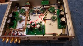
Two boards to left and right are CLCRC filters for the frontend, and I agree the mid bottom board seems to be the supply for the output 6080 tubes and initial a B+ into the left and right CLCRC boards. The heaters appear to be AC directly off the transformer (slots in the middle of the picture). The 100uF cap provides the first initial filter in parallel with all the other supplies - the larger caps are fed after the resistor thus part of a RC filter for the output tubes.
Last edited:
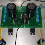
I think the two 330uF capacitors on the mid bottom board are the output capacitors. On the first picture the wires to the jackplug can be seen.
It's hard to make out so I'm not sure about the following. But I get the impression that the current of this power supply is going from the "B+" terminals on the mid bottom circuit board to pins 7, and possibly also pins 1, of the 6CA4's. If true, than the the two diodes in the 6CA4 are paralleled, passing already rectified current. Gives a small delay at start-up though.
It's hard to make out so I'm not sure about the following. But I get the impression that the current of this power supply is going from the "B+" terminals on the mid bottom circuit board to pins 7, and possibly also pins 1, of the 6CA4's. If true, than the the two diodes in the 6CA4 are paralleled, passing already rectified current. Gives a small delay at start-up though.
I think the two 330uF capacitors on the mid bottom board are the output capacitors. On the first picture the wires to the jackplug can be seen.
It's hard to make out so I'm not sure about the following. But I get the impression that the current of this power supply is going from the "B+" terminals on the mid bottom circuit board to pins 7, and possibly also pins 1, of the 6CA4's. If true, than the the two diodes in the 6CA4 are paralleled, passing already rectified current. Gives a small delay at start-up though.
Good point - I can see the 6080 to 'out' on the left. So the B+ for both output and smaller tubes are handled on the side boards.
I've been looking at circlotrons too long.