Hi JeffYoung,
Large capacitors like this are often connected between two large copper planes with GND being on one side of the board and VBUS being on the other (or on internal layers). The "wheels" are thermal reliefs which help to thermally decouple the capacitor pads from the large planes, which improves solderability.
In the example you posted it makes no sense to have them as there are no planes connected to the pads of the capacitor. My guess is that they are integrated into the actual footprint for the part, which is pretty oldschool given that almost every PCB program on the planet will automatically generate thermal relief pads on request.
For mass production, there is no need for thermal reliefs at all since wave soldering makes them unnecessary. They are only of use for traditional soldering irons and hand soldering.
As a side note, please excuse Scott's crude, belittling, and totally unhelpful response to what is a perfectly valid question. Maybe he hadn't had his morning coffee yet.
Regards,
Owen
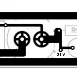
PCB designs often have an outer ring around a capacitor pad, with spokes connecting the ring to the pad (see attached image). What's the purpose of this?
Thermal relief for soldering and desoldering... Important when making a proper connection.
See page 12 of this article and then let the internet be your friend.
http://www.eurocircuits.com/wp-cont...small-batch-services/ec-design-guidelines.pdf
As an alternative theory, that pad symbol was used in old school PCB software to indicate mounting screws.
FWIW I still keep a dedicated XP machine to run DOS Protel Autotrax and Tango PCB, for the very good reason that I stsrted using them commercially in 1989 and have hundreds of designs of which now and then somebody needs one, and those pads are in the menu.
So *maybe* PCB designer wanted to indicate that screw mount capacitors may be used there.
What does that PCB snippet belong to?
Thanks again to Owen and Thomas.
While the thermals are harmless (if useless) in the posted example, I went over another of my designs which does have a ground plane and could no doubt use some thermals.
Cheers,
Jeff.
While the thermals are harmless (if useless) in the posted example, I went over another of my designs which does have a ground plane and could no doubt use some thermals.
Cheers,
Jeff.
What does that PCB snippet belong to?
It's from Nelson Pass' F3. It's a pretty small cap (25mm diameter), so I don't think it's for screw-mount. (The FirstWatts are hand-soldered, but by-and-large don't have ground planes, so nothing suggestive one way or the other there.)
If you have ever tried to manually desolder the negative (can) terminal on an elco soldered to a ground plane you will appreciate the use of thermal reliefs.
If you have ever tried to manually desolder the negative (can) terminal on an elco soldered to a ground plane you will appreciate the use of thermal reliefs.
He he... yeah, desoldering fails to make my list of "fun" even in the best of circumstances. 😉
It's from Nelson Pass' F3. It's a pretty small cap (25mm diameter), so I don't think it's for screw-mount. (The FirstWatts are hand-soldered, but by-and-large don't have ground planes, so nothing suggestive one way or the other there.)
Ok, I had no size scale reference, so it *might* have been a large cap, also saw it as "pretty large for a plain thermal relief", now knowing it´s a 25mm cap, those legs are barely 500 mils away, so each pad isn´t that large.
Personally I would have used a somewhat smaller but solid one but hey, to each his own 🙂
- Status
- Not open for further replies.
- Home
- Design & Build
- Construction Tips
- What's the purpose of the "wheel" under capacitors?