PRR gives good advice. Try it.
Yes good advice ... but I can't try it bcoz I have already disconnected the board from the wiring. 🙁
I assume you have already checked DC voltages to confirm that all the devices are apparently working?
Yes and that's the strange thing. Drain voltage on the 2nd stage appears to be normal ... just there's no signal coming through. 😡
But it was working before this problem appeared! 🙁
Andy
You can short the cap, but you cannot touch one end of it? I don't understand.andyr said:Yes good advice ... but I can't try it bcoz I have already disconnected the board from the wiring.
You need to make a test harness, so you can really analyze your problem with the board out where you can see it and flip it over.
Power supplies in, signal in, four wires, not a big problem.
If the signal gets through the circuit to the out pins, you win.
A wall transformer for the voltage in may help the situation some. This doesn't even have a split supply does it? I pick them up at the charity resale shop for $1-2.
Trace the voltage with a scope or 50x gain op amp circuit into a VOM meter. Make a signal source out of a transistor radio, a dead earbud harness, a resistor divider to get down to mag phono voltage levels.
The last two are time consuming, but the tools remain after the problem is fixed for the next adventure.
Last edited:
You can short the cap, but you cannot touch one end of it? I don't understand.
Sure, I can touch both ends of the cap but I had already taken the board out of the case ... so it is no longer powered up.
You need to make a test harness, so you can really analyze your problem with the board out where you can see it and flip it over.
That's a nice idea - I'll think about that for the future.
🙂
Power supplies in, signal in, four wires, not a big problem.
Haha - I wish. Actually, this case has 4x phono stage boards in it - L & R channels for MC & MM. So there are a total of 16 signal wires and 16 ground wires between the board and the case which need to be unsoldered & then re-soldered. Power wires from the battery use spade connectors - so that's easy ... but there are 16 of those. 🙂
Thanks again, guys - I'll bring out the CRO and the sig-gen at the weekend, powering the faulty board with some spare batteries.
Andy
> Drain voltage on the 2nd stage appears to be normal
Perfectly reasonable.
First you must get the devices to a happy operating point, DC bias.
Then you connect Audio in and out without upsetting that DC bias.
About half the parts set-up the DC, others pass the audio.
In trouble-shooting, generally we *first* look at the DC conditions, because a DC meter is simple/quick. Around half of all faults may be spotted this way.
When the DC is fine, but audio don't get through, we look at the audio coupling parts (mostly caps these days).
By your reported symptoms, that cap is "not there". It looks like it is there, but it isn't capping like a cap should. For these type caps, internal failure (open weld) is unlikely but not impossible. Bad solder is often The #1 Problem in electronics!! Solder may be blobbed all around the joint, but a layer of tarnish on the lead or pad means no metal-to-metal connection. Often a joint "works for a while" (even decades) by a hair-width contact, which finally lets go.
> I'll bring out the CRO
Don't need a bulldozer to plant petunias. You have clear signal one side, "no" signal the other side. What can the CRO add to that? A good picture of "no signal"?
But only one channel has a problem. Wire up the one channel. Four wires. Six with output connected to power amp.Haha - I wish. Actually, this case has 4x phono stage boards in it - L & R channels for MC & MM. So there are a total of 16 signal wires and 16 ground wires between the board and the case which need to be unsoldered & then re-soldered. Power wires from the battery use spade connectors - so that's easy ... but there are 16 of those. 🙂
When the bad channel now works properly, then wire up the 16 wires again.
By your reported symptoms, that cap is "not there". It looks like it is there, but it isn't capping like a cap should. For these type caps, internal failure (open weld) is unlikely but not impossible. Bad solder is often The #1 Problem in electronics!! Solder may be blobbed all around the joint, but a layer of tarnish on the lead or pad means no metal-to-metal connection. Often a joint "works for a while" (even decades) by a hair-width contact, which finally lets go.
Well, a bit of fiddling around with the multimeter set to 'continuity' showed up the culprit. 🙂
Not a dry solder joint ... a joint that I had forgotten to solder! 😱
As you said - it worked for a while ... and then stopped working. 🙁 The coupling cap goes from the end of the passive all-in-one RIAA network to the Gate of the 2nd gain stage - and I had merely connected the wires at the input end of the cap ... not soldered them together. 🙁
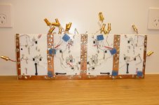
See attached pic ... I use 1/8" teflon board to hold the components in place and then solder the component leads together on the underside of the teflon. Before I apply solder, I bend the connecting wires together - and I had missed applying solder to this one joint. After applying solder, I rigged up a temporary battery supply to this one channel and checked with the CRO that signal was passing. Now to re-assemble the board into its case.
Anyway, thanks to everyone for their input. (The coupling caps will stay, to get rid of any DC offset)! 🙂
Andy
Attachments
Last edited:
- Home
- Amplifiers
- Solid State
- What's the problem with DC offset?