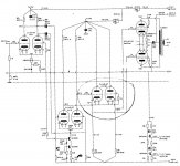
I have been building up the driver circuit for the Morgan Crystal Palace Amplifier. I am perplexed how the Cathode Follower works in this circuit. In my tests, the input to the grid of the cathode followers (shown circled in the attached image) is 170Vpp (58Vrms), 1kHz, and the cathode output is 160Vpp(56Vrms). The grid is biased -8V (90V-82V).
Since the grid is only biased at -8V, why doesnt the output get clipped when the input voltage swings beyond the -8V? What is the physics explanation?
Since the grid is only biased at -8V, why doesnt the output get clipped when the input voltage swings beyond the -8V? What is the physics explanation?
Attachments
The cathodes are at -82VDC. They can swing up and down from there,
following along with their grids.
The Valve Wizard
following along with their grids.
The Valve Wizard
Last edited:
D'Oh! Now I see how the 100% feedback works. I never actually thought about how it works before. Thanks. Your reply addressed my question. I am now enlightened.