I would like to build an esl of about 0.2 meters x 1.5 meters with wires stators (someone can tell me where to download the software esl_seg_ui?) what is the right size of the spacers for a 1: 100 transformer?
I would like to build an esl of about 0.2 meters x 1.5 meters with wires stators (someone can tell me where to download the software esl_seg_ui?) what is the right size of the spacers for a 1: 100 transformer?
The right size gap depends not only on the transformer, but how big an amplifier you plan to use and how low in frequency you want the ESL to play. Are you building a hybrid? or full range design. If you are unsure of what direction you are headed at the moment, something around 2mm would be a good starting point.
You can find download links in the first post of the esl_seg_ui thread:
Segmented Wire Stator ESL simulator (esl_seg_ui)
For the English Translation version: (thanks again Bazukaz!)
See Post#39 for download files and Post#75 for step-by-step instructions on how to get it running.
thank tou very much, my amplifier is near 50 watts....do you think it's too low for a 1:100 transformer? I already have a subwoofer up to 120 - 150 hertz so I would be happy if the esl goes down to that frequency
<<Moving response from another thread here, since it is specific to the panel you are building.>>
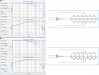
Since you are working on a hybrid, you can pick up even more sensitivity be reducing the air-gap to the more common 1.5mm size and setting bias voltage to 3.5kV – 4.0kV. I was actually working up this example as a good starting point for you when I saw you had posted yours. Attached are schematics and response for both.
Yes, I think for 42 wires what you have is a very good starting point for a hybrid ESL. As CharlieM did, you will likely not need to use the 12K resistor for the center segment. Instead, set them to 0 ohm and adjust the value of the nominally 1 ohm damping resistor on the primary side of the transformer for flat high frequency response. Since your step-up transformer only has a ratio of 75:1 and you show a 2mm air-gap, you can pick up some more sensitivity by increasing the bias voltage a bit above the recommended 4kV to something like 5kV – 5.5kV.played with the spreadsheet and esl_seg_ui in this week this configuration with seven segments (42 wires) seem to be interesting (with normal commercial resistors values...) it's a good starting?
Since you are working on a hybrid, you can pick up even more sensitivity be reducing the air-gap to the more common 1.5mm size and setting bias voltage to 3.5kV – 4.0kV. I was actually working up this example as a good starting point for you when I saw you had posted yours. Attached are schematics and response for both.
Attachments
- Status
- Not open for further replies.