Hi X
Just wondering...after reviewing your “how to” of mounting the LU1014D onto the IMS boards...am I brave enough to risk the few parts I’ll end up with on a frying pan.
I don’t have any SMD experience besides using a soldering iron to wet pads for a few SMD parts and then setting them reflowing with the iron and solder if needed.
No hot air or paste experience.
Not sure the soldering iron reflow would work with your boards.
Any advice?
And I thought I was the only one crazy enough to literally "cook up" some SMD boards in a frying pan. I used a similar pan on a $15 "Aroma" brand hot plate that I got from Amazon.
I was advised that the fumes coming from overheated Teflon are quite toxic, so I switched to a piece of 0.100 inch thick aluminum held in a pair of Vise Grips. I think it works better since it is flatter. As soon as the solder reflows I move the aluminum from the hot plate to a large heat sink for cooling.....
Great idea George! Sometimes the pcb I’m soldering is just big enough to hit the curve in the base of the pan lifting it slightly, not good. I’ll whip out some aluminum plate next time.

Some tips I posted earlier on how to find out more info from YouTube videos
BTSB Buffer - SE/Bal to SE/Bal Buffer GB
Tools and supplies:
BTSB Buffer - SE/Bal to SE/Bal Buffer GB
Video of me applying paste and hot air:
XRKaudio SMT Method Demo - YouTube
Video of me heating the IMS TO247 adapter boards on skillet and applying hot air:
Reflow soldering LU1014D?s onto aluminum IMS TO247 adapter boards - YouTube
For the Lu1014D adapter boards use Sn63/Pb37 no clean solder paste - I used MG Chemicals brand but Chipquick and Kester also make it.
Most important things with older eyes are binocular magnifiers and good tweezers. Spend at least $20 on your tweezers. They are extensions of your fingers and good ones make a difference. You don’t need them for the LU1014 adapter but if you intend to make more SMT circuits they are essential.
BTSB Buffer - SE/Bal to SE/Bal Buffer GB
Tools and supplies:
BTSB Buffer - SE/Bal to SE/Bal Buffer GB
Video of me applying paste and hot air:
XRKaudio SMT Method Demo - YouTube
Video of me heating the IMS TO247 adapter boards on skillet and applying hot air:
Reflow soldering LU1014D?s onto aluminum IMS TO247 adapter boards - YouTube
For the Lu1014D adapter boards use Sn63/Pb37 no clean solder paste - I used MG Chemicals brand but Chipquick and Kester also make it.
Most important things with older eyes are binocular magnifiers and good tweezers. Spend at least $20 on your tweezers. They are extensions of your fingers and good ones make a difference. You don’t need them for the LU1014 adapter but if you intend to make more SMT circuits they are essential.
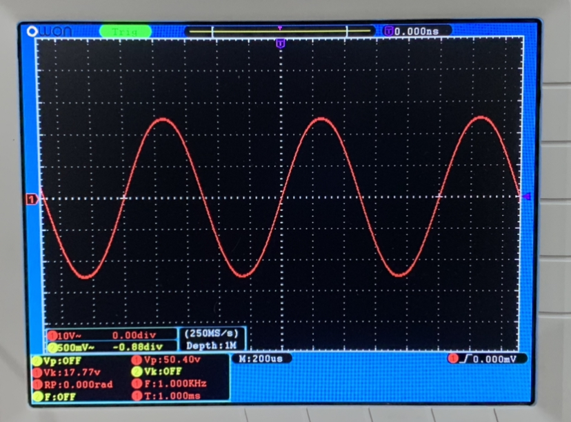
WOBT May 26, 2021 - Max power test of LuFo. I managed to get 17.77vrms into 8ohms. That’s 39.5w. As predicted and before onset of clipping.
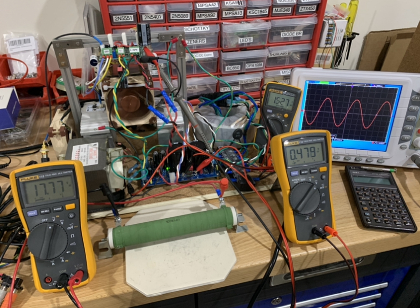
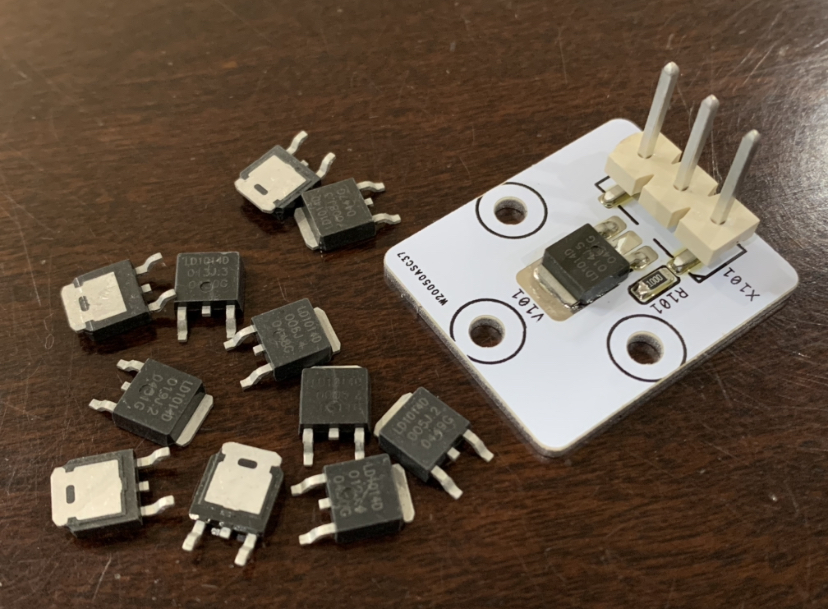
WOBT - May 27, 2021: I got a shipment of LD1014D’s (SMT version of LU1014D) from AliExpress based on a tip from Danny66 that they tested out to be genuine’s. I installed them on my aluminum IMS PCB adapter. It was so much easier to install these without having to bend the pins. They installed just fine. Then I quickly installed them in the LuFo amp to make sure they work. The bias current set up real nice and stable. The music sounds great. Running about 2.9A and Vs about 1.53v.
Here is is installed in the heatsink for the LuFo:
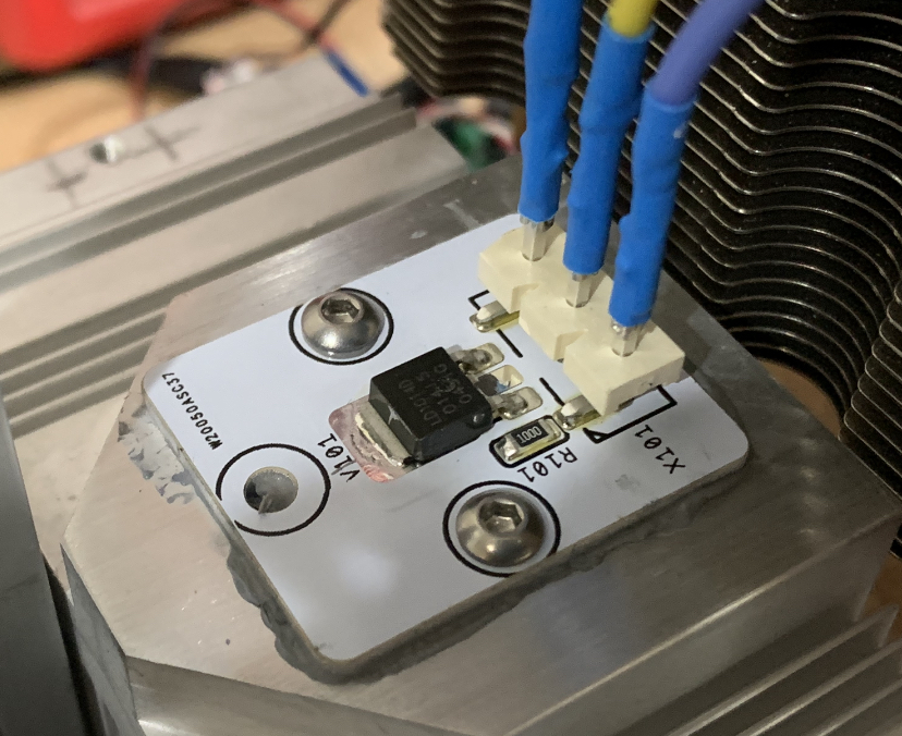
Here is is installed in the heatsink for the LuFo:
Last edited:
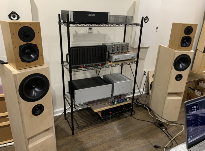
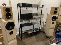
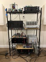
WOBT - May 28, 2021: Some lab cleanup to the front of the house mess. I got a 4 level wire shelf from HD (350lb capacity per shelf) and this let me populate all 7 working amps. I got a couple of new amps today for evaluation. A GaN Class D from LSA, and a tube amp from Line Magnetic. Here is the new rack of amps:
The LM-211ia makes a fine glow. Listening to it now - sounds very nice with the TLs:
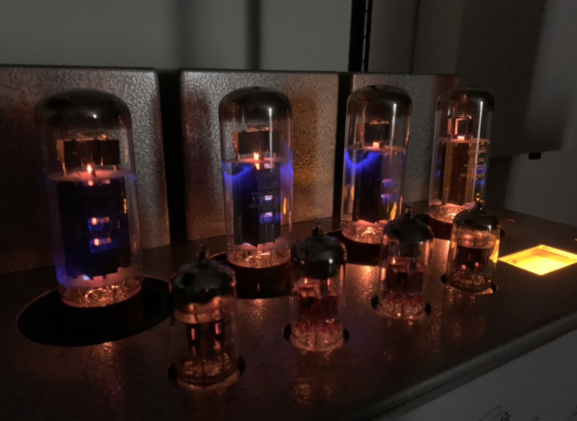
The LM-211ia makes a fine glow. Listening to it now - sounds very nice with the TLs:
Attachments
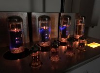
I have only used if maybe 4hrs at a time. It does radiate a lot of heat from the tubes. But the chassis seems fine. I have not had any issues. This amp has been around a long time so I would imagine any over heating issues would be fixed by now.
WOBT - June 1, 2021: Listening to my amps on their new rack. Am I the only one who installs his amps backwards, or butt-out? For me, it makes no sense to put the front panels in front as I like to listen to different amps routinely. Much easier to use the rear side of the amps like a patch panel by plugging in the RCA's and speaker cables directly rather than reaching around the back of the rack. The only one not butt-out is the LM 211ia which has an IR remote control receiver window on the front panel.
Playing tonight is the Pass DIYA Sony VFET amp (s/n 010) on the lower right. A full 10w into 8ohms but it sounds very nice. I am driving it with a special hybrid tube buffer preamp with 14dB gain.
Playing tonight is the Pass DIYA Sony VFET amp (s/n 010) on the lower right. A full 10w into 8ohms but it sounds very nice. I am driving it with a special hybrid tube buffer preamp with 14dB gain.
Attachments
WOBT - June 2, 2021: for grins I decided to connect my full range TG9FD flat BIB (FIB) foam core speaker to my LM-211ia tube amp. Played some jazz. It sounds pretty darn good! The imaging was superb. The balance and mid range was smooth and lush. Very nice.
Flat BIB (FIB) speaker with TG9FD and LM-211ai tube amp - YouTube
Flat BIB (FIB) speaker with TG9FD and LM-211ai tube amp - YouTube
M2x / Yarra Pre experimenter board
Hi xrk971
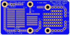
I made a little experimenterboard in Kicad for the M2x / Yarra format pre amplifiers.
This way i can experiment with dead-bug style pre amplifiers.
Could you take a short look and give me some feedback. I am learning Kicad on the go. Maybe your blessing ??
Hi xrk971
I made a little experimenterboard in Kicad for the M2x / Yarra format pre amplifiers.
This way i can experiment with dead-bug style pre amplifiers.
Could you take a short look and give me some feedback. I am learning Kicad on the go. Maybe your blessing ??
Attachments
Hi Puijkh,
Wow - very cool! I was just going to ask JPS64 to make something similar to this. Of course, you are free to design this - I just ask that you make the Gerbers freely available. I do have a request - can you put a standard SOIC-8 pad with breakouts somewhere in the middle? Also, for the +ve and -ve PSU bolts, please add holes for say 100uF, 35v rail caps and 100nF X7R bypass caps? Double check your bolt hole locations. The horizontal spacing on the the 4 bolts looks compressed.
Thanks!
xrk971
Hi xrk971,
Will update the experimenter board to v2 with suggested additions.
I will make the gerbers available together with the Kicad files on github (or any other place if more handy)
Might you have a mechanical spec for me for the mounting/signal holes.
I cobled it together from measured screenshot together with a M2x gerber.
😀 😕
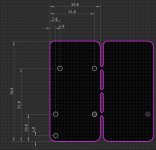
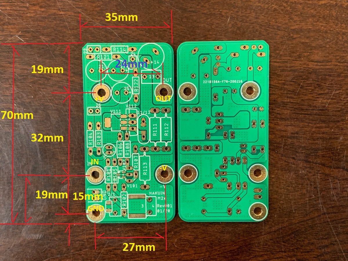
Here is what I have for the board dimensions using a dial caliper. JPS64 might have corrections. The holes are all for usial M3 screw clearances (about 3.25mm dia). Board is 70mm x 35mm. Four holes are 32mm (Long) x 27mm W (larger) x 24mm W (smaller). GND hole in corner is 15mm offset. Board has 19mm overhangs on each end.
Attachments
Thanks xrk971,
You saved my day, i had the same measurements,
but no the same calculations 😱
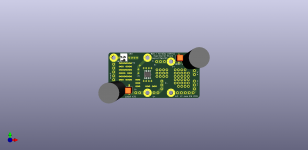
So V3 is in production @ JLC, so the waiting started.
In the mean time, the M2x from diyaudio store is on the move to me.

You saved my day, i had the same measurements,
but no the same calculations 😱
So V3 is in production @ JLC, so the waiting started.
In the mean time, the M2x from diyaudio store is on the move to me.
I have stored the kicad project for the M2x / Yarra Pre Experimenter board with the generated gerbers at
GitHub - puijkh/Yarra_Experimenter_PCB: A M2x Yarra Pre Experimenter PCB
So if anyone wants to change the board or produce there own, be my guest 😎
I am now waiting for some boards (The experimenter, an ACA board set, M2x from diyaudio shop) to turn up on my bench, time to clean up and make some room on the bench 😀
Hi Puijkh,
If your planning to use the Yarra/M2X mounting pattern, the V- is not in the correct position.
If your planning to use the Yarra/M2X mounting pattern, the V- is not in the correct position.