I thought it would be interesting to have a thread where I could talk about what’s OBT (on the bench tonight) - or what do I have to work on. A good chance to show what sort of projects and stuff I am working on.
I also invite folks to post their stuff here if they want - especially if it involves stuff from my shop!
I know there are folks working on FH9HVX, Alpha Nirvana, SLBs, SFPs, Aksa Lender’s, Yarra’s, and Rockville speakers, 10F/RS225 TL speakers, foam core builds, etc. please share what you are working on Tonight!
To kick it off, here is what I will be doing: some SMT reflow soldering of the LU1014D power JFET (I think it is a SIT) TO-247 IMS adapter boards. These will be a test batch to check to make sure they work. There is a GB here - I won’t be running it and the boards can be ordered by anyone as the Gerbers are posted free for all to use.
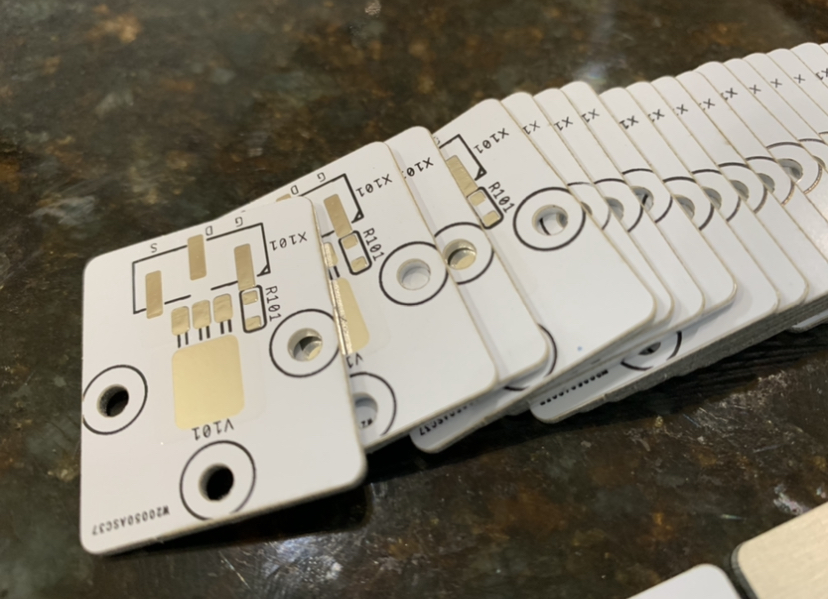
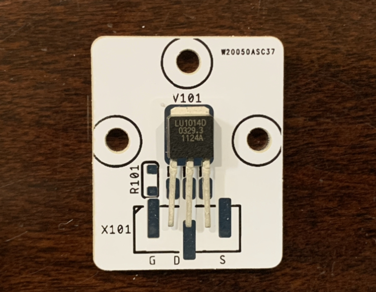
Woofertester has sent me a batch of matched LU1014D’s to install on these boards. These aluminum substrate boards will allow these peculiar power JFETs to be mounted in an underhung fashion like a conventional TO-247 MOSFET. They should be much easier to use. Also, Nelson Pass is giving away a bag of these unobtanium SITs to they DIYA community. Woofertester is doing the matching and WG45 is handling the GB. Thanks to JPS64 for the awesome layout of this metal substrate adapter board. Thanks to Nelson Pass and Woofertester for the LU1014D’s, and thanks to WG45 for handling the GB that is off to a roaring great start. I can’t believe we have 101 pairs of these adapter boards on the interest list already!
So that’s What’s OBT for me.
What’s OBT for you guys? 🙂
I also invite folks to post their stuff here if they want - especially if it involves stuff from my shop!
I know there are folks working on FH9HVX, Alpha Nirvana, SLBs, SFPs, Aksa Lender’s, Yarra’s, and Rockville speakers, 10F/RS225 TL speakers, foam core builds, etc. please share what you are working on Tonight!
To kick it off, here is what I will be doing: some SMT reflow soldering of the LU1014D power JFET (I think it is a SIT) TO-247 IMS adapter boards. These will be a test batch to check to make sure they work. There is a GB here - I won’t be running it and the boards can be ordered by anyone as the Gerbers are posted free for all to use.
Woofertester has sent me a batch of matched LU1014D’s to install on these boards. These aluminum substrate boards will allow these peculiar power JFETs to be mounted in an underhung fashion like a conventional TO-247 MOSFET. They should be much easier to use. Also, Nelson Pass is giving away a bag of these unobtanium SITs to they DIYA community. Woofertester is doing the matching and WG45 is handling the GB. Thanks to JPS64 for the awesome layout of this metal substrate adapter board. Thanks to Nelson Pass and Woofertester for the LU1014D’s, and thanks to WG45 for handling the GB that is off to a roaring great start. I can’t believe we have 101 pairs of these adapter boards on the interest list already!
So that’s What’s OBT for me.
What’s OBT for you guys? 🙂
Last edited:
As promised... WOBT for May 18, 2021:
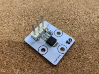
Installation of LU1014D's on TO-247 Al IMS adapter PCBs.
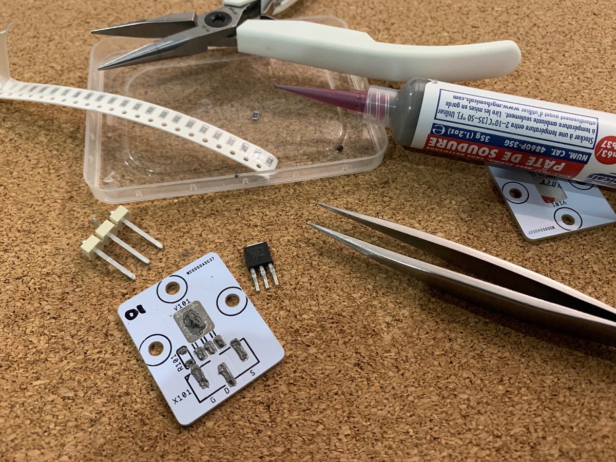
I am using MG Chemicals Sn63/Pb37 Leaded No-Clean Solder Paste with 20ga tapered plastic nozzle applicator. First a clean with isopropyl alcohol and paper towel. Applied paste, installed the LU1014D, 100R 1206 resistor, and the Samtec 0.200in pitch SMT header pins. The only fiddly thing was figuring out how to bend the legs to sit flush with the PCB. It took some practice but I figured it out. Using my trusty Lindstrom needle nose pliers to do a Z bend then snipping the legs off to the proper length.
Here is the setup:
Here is what the parts look like installed on wet solder paste:
Here is what they look like on the hot plate - IMS PCB's heat up almost instantly and really no need for the hot air from the top. The solder melted almost immediately. I used some tweezers to nudge the parts into good alignment as the surface tension moves them around a bit. I probably had too much past on the thermal pad:

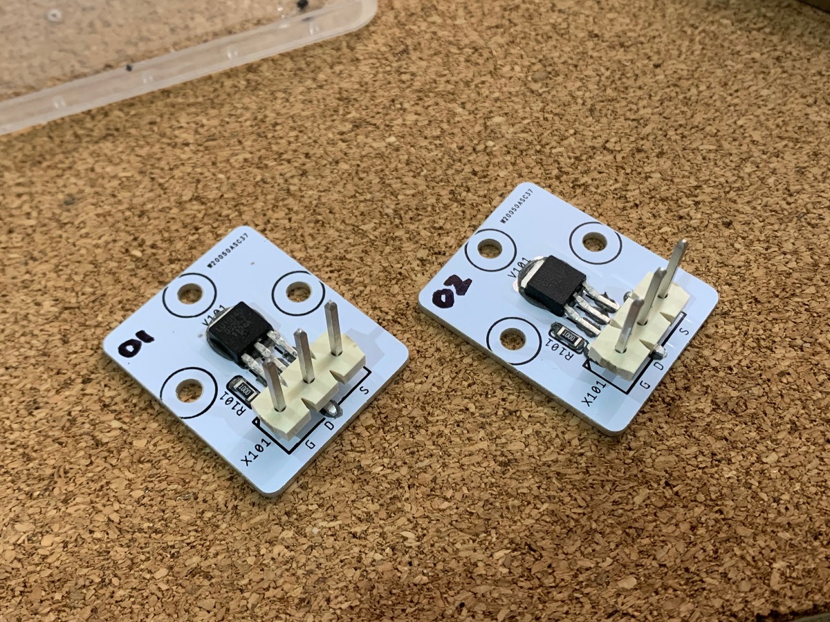
Here is what they look like after reflowing at about 240C for 30 seconds. I cooled the pan off on a wet towel underneath while fanning the part with a piece of cardboard - all done:

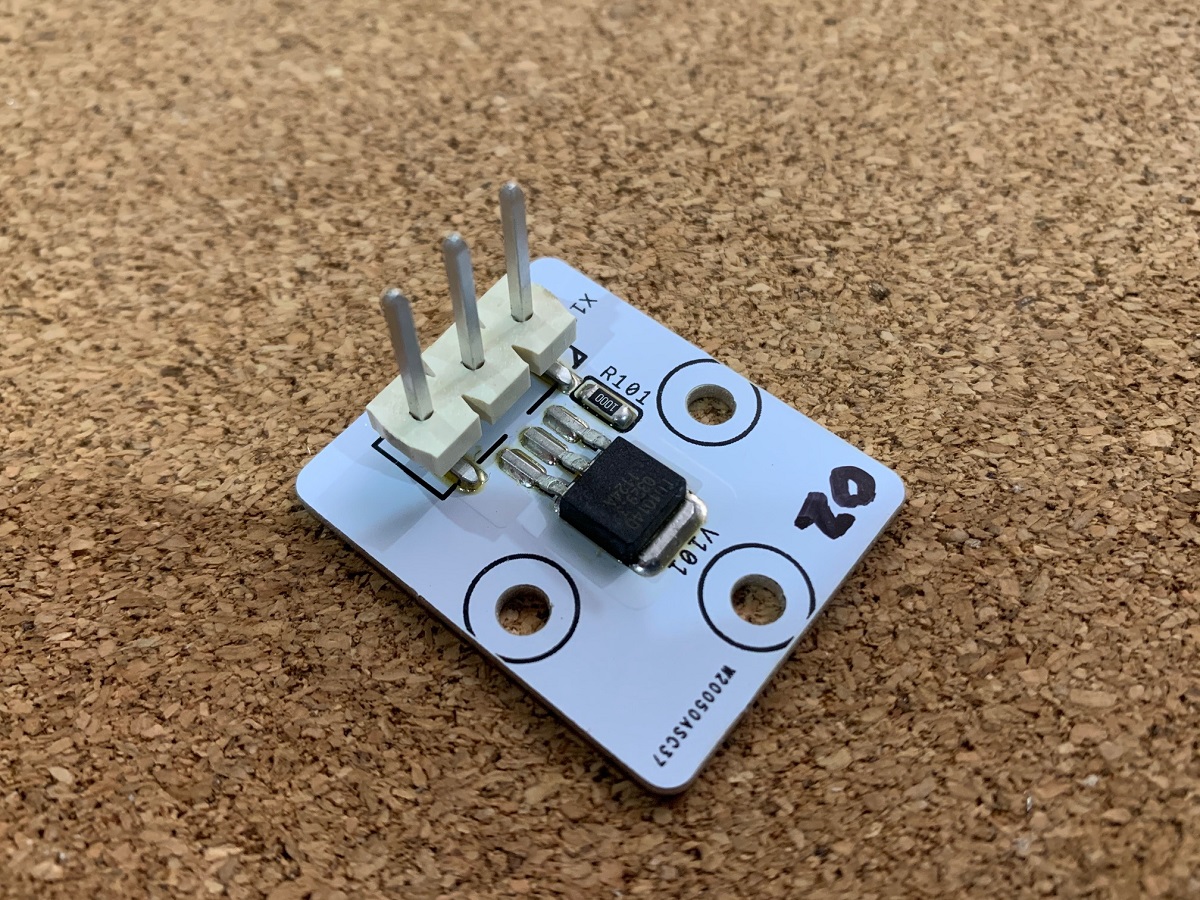
Here is a closeup of the joints, looks pretty good and with nice fillets:
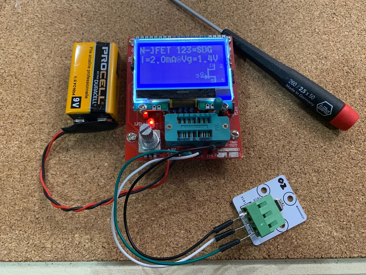
Connected it to a component tester and it show up as an N JFET - so all is good, I did not cook it 🙂:
I guess the next test is to set it up with the gate (G) shorted to the source (S) pin and place a low value circa 1-2ohm power resistor between S and Gnd. Then apply regulated 3Vdc to the Drain (D) pin and measure the current across the resistor. Check to see that the heat is dissipating properly.
So this is looking promising - and I think that this is something an average DIY'er can do with a basic skillet and electric hot plate set to LOW.
This is a similar paste (smaller quantity for the average DIYer):
https://www.amazon.com/Clean-Leaded-Solder-Paste-Grams/dp/B017RSZFQQ/
I actually used this one - a much bigger volume:
https://www.amazon.com/MG-Chemicals-Leaded-Solder-Paste/dp/B00TIC895Y
Installation of LU1014D's on TO-247 Al IMS adapter PCBs.
I am using MG Chemicals Sn63/Pb37 Leaded No-Clean Solder Paste with 20ga tapered plastic nozzle applicator. First a clean with isopropyl alcohol and paper towel. Applied paste, installed the LU1014D, 100R 1206 resistor, and the Samtec 0.200in pitch SMT header pins. The only fiddly thing was figuring out how to bend the legs to sit flush with the PCB. It took some practice but I figured it out. Using my trusty Lindstrom needle nose pliers to do a Z bend then snipping the legs off to the proper length.
Here is the setup:
Here is what the parts look like installed on wet solder paste:
Here is what they look like on the hot plate - IMS PCB's heat up almost instantly and really no need for the hot air from the top. The solder melted almost immediately. I used some tweezers to nudge the parts into good alignment as the surface tension moves them around a bit. I probably had too much past on the thermal pad:
Here is what they look like after reflowing at about 240C for 30 seconds. I cooled the pan off on a wet towel underneath while fanning the part with a piece of cardboard - all done:
Here is a closeup of the joints, looks pretty good and with nice fillets:
Connected it to a component tester and it show up as an N JFET - so all is good, I did not cook it 🙂:
I guess the next test is to set it up with the gate (G) shorted to the source (S) pin and place a low value circa 1-2ohm power resistor between S and Gnd. Then apply regulated 3Vdc to the Drain (D) pin and measure the current across the resistor. Check to see that the heat is dissipating properly.
So this is looking promising - and I think that this is something an average DIY'er can do with a basic skillet and electric hot plate set to LOW.
This is a similar paste (smaller quantity for the average DIYer):
https://www.amazon.com/Clean-Leaded-Solder-Paste-Grams/dp/B017RSZFQQ/
I actually used this one - a much bigger volume:
https://www.amazon.com/MG-Chemicals-Leaded-Solder-Paste/dp/B00TIC895Y
Attachments
-
 LU1014D-TO247-Adapter-Install-01.jpg505.5 KB · Views: 7,170
 -
 LU1014D-TO247-Adapter-Installation-06.jpg568.2 KB · Views: 6,439
 -
 LU1014D-TO247-Adapter-Installation-05.jpg478.7 KB · Views: 7,446
 -
 LU1014D-TO247-Adapter-Installation-04.jpg523.4 KB · Views: 6,495
 -
 LU1014D-TO247-Adapter-Installation-03.jpg415.4 KB · Views: 6,058
 -
 LU1014D-TO247-Adapter-Install-02.jpg558.4 KB · Views: 7,003
Last edited:

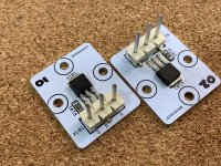
WOBT - May 19, 2021: installing the LU1014D TO247 adapters onto a heatsink and testing thermal performance.
I mounted the heatsinks earlier today. Surplus HP CPU coolers and some M3 drill and tap, thermal paste, it’s looking really good.
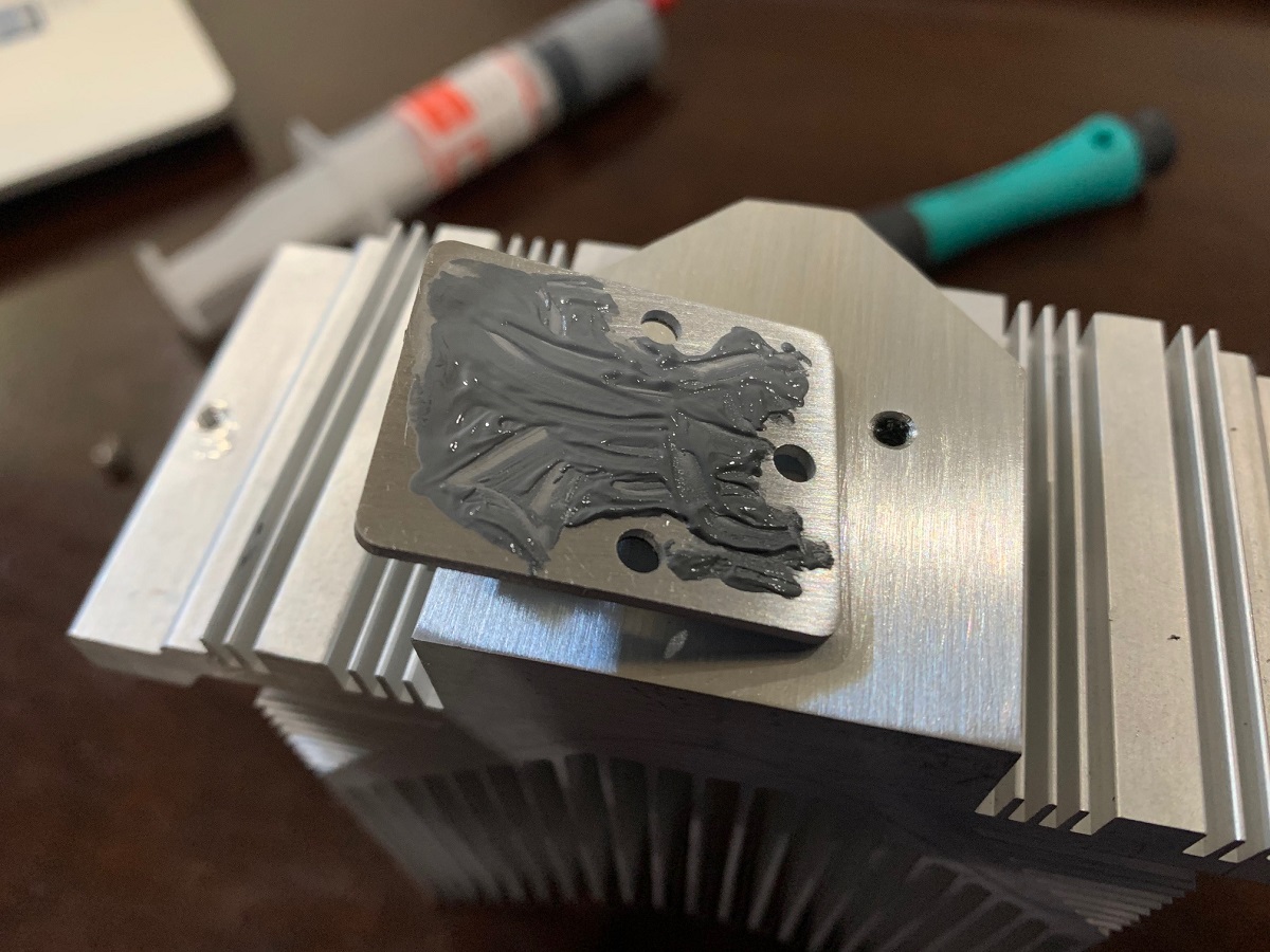
I mounted the heatsinks earlier today. Surplus HP CPU coolers and some M3 drill and tap, thermal paste, it’s looking really good.
Last edited:
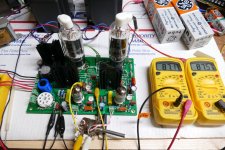
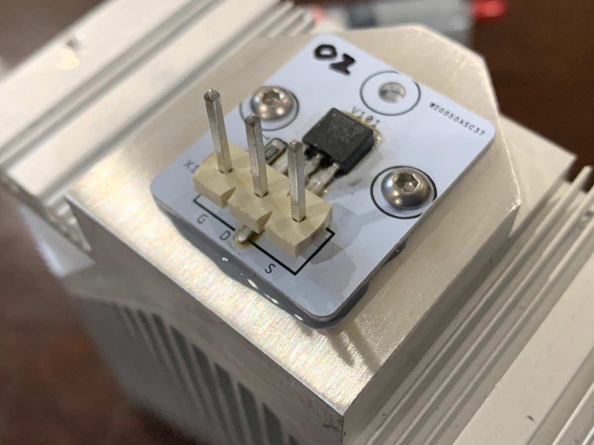
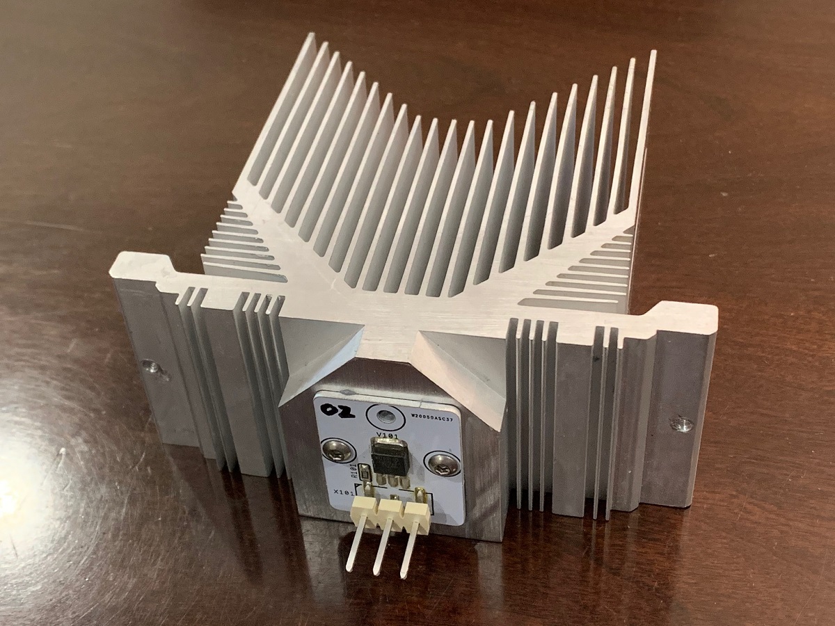
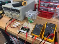
Thermal Testing of the LU1014D TO-247 adapters
I made a little rig with a screw terminal block and some 10w 2% cement filled crossover resistors (2.7ohm, 2.0ohm, 1.0ohm) from Source to GND, a 9k1 resistor from Gate to GND, and a regulated bench supply of 3v to the Drain. I monitor voltage across the Source resistor to check the bias current.
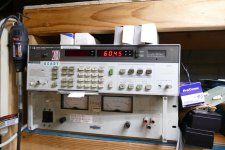
Here is the setup showing the GPC Instek 3020 linear bench PSU:

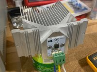
Here is a closeup of the TO-247 adapter mounted to the heatsink with a screw terminal block used to bring the wires to the pins:

Here is a closeup of the test setup showing the resisotors and Fluke 101 and 115 DMM's used to measure the voltages. Shown here is the 1.0 ohm resistor case at 7.3v Vdrain:
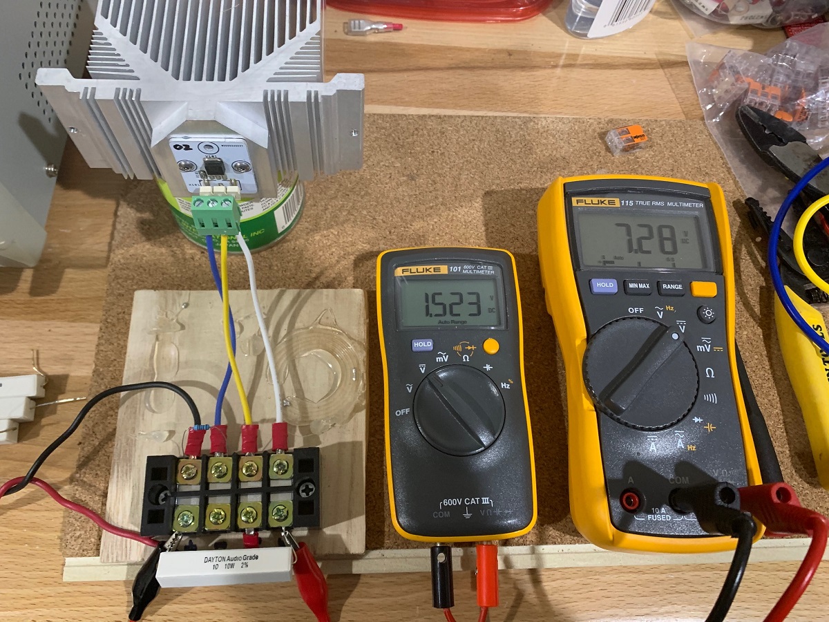

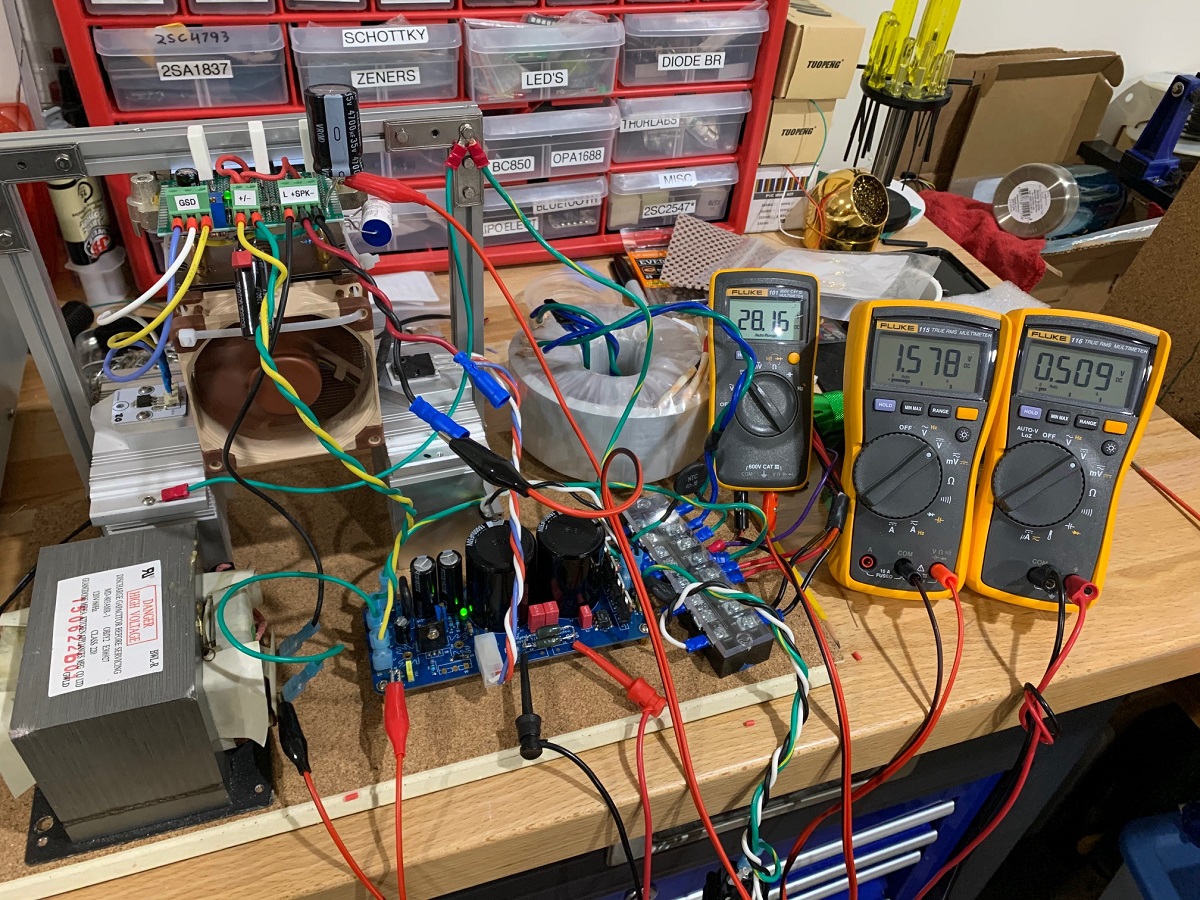
So, I think that this demostrates that the IMS PCB adapter works very well to transfer heat from the device and is easy to use. I also see that the LU1014D can handle 1.5A bias current easily. This will be pretty handy and we know that we need about 5.75v across the Drain to Source with a 1ohm Source resistor to achieve a 1.5A bias current.
I made a little rig with a screw terminal block and some 10w 2% cement filled crossover resistors (2.7ohm, 2.0ohm, 1.0ohm) from Source to GND, a 9k1 resistor from Gate to GND, and a regulated bench supply of 3v to the Drain. I monitor voltage across the Source resistor to check the bias current.
Here is the setup showing the GPC Instek 3020 linear bench PSU:
Here is a closeup of the TO-247 adapter mounted to the heatsink with a screw terminal block used to bring the wires to the pins:
Here is a closeup of the test setup showing the resisotors and Fluke 101 and 115 DMM's used to measure the voltages. Shown here is the 1.0 ohm resistor case at 7.3v Vdrain:
- For 3.0v at the Drain pin and 2.7ohm resistor, we get about 0.35A and the device is barely warmer than ambient. The heatsink works really well.
- For 2.0ohm, we get 0.48A at 3.0v and temps still very close to ambient.
- Fort 1.0ohm, we get 0.93A at 3.0v and temps maybe 1 to 2C above ambient.
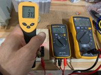
- I decided to crank up the voltage to 7.28v at the Drain and got 1.52A and the temps rose. The device temp was 37C, the heatsink temp was 25C (ambient 23C), and the resistor was 62C. The heatsink looks like it was keeping its cool well at 8.6w dissipation:
So, I think that this demostrates that the IMS PCB adapter works very well to transfer heat from the device and is easy to use. I also see that the LU1014D can handle 1.5A bias current easily. This will be pretty handy and we know that we need about 5.75v across the Drain to Source with a 1ohm Source resistor to achieve a 1.5A bias current.
Attachments

Last edited:
Stunning work and great photos X! Are these photos taken with a cell phone camera under artificial light (since you work at night when we sleep)? As a matter of interest - what kind of hot plate do you use? Is it a non-stick frying pan on an inductor stove?
Sorry for all the questions, but I admire your work.
BTW, my bench looks terrible currently - couple of unfinished projects nobody would like to see.
Sorry for all the questions, but I admire your work.
BTW, my bench looks terrible currently - couple of unfinished projects nobody would like to see.
Hi Twocents, thanks!
My camera is iPhone XR and lighting is overhead recessed flood light bulbs fitted with 60w equivalent LED bulbs 5200K color temp.
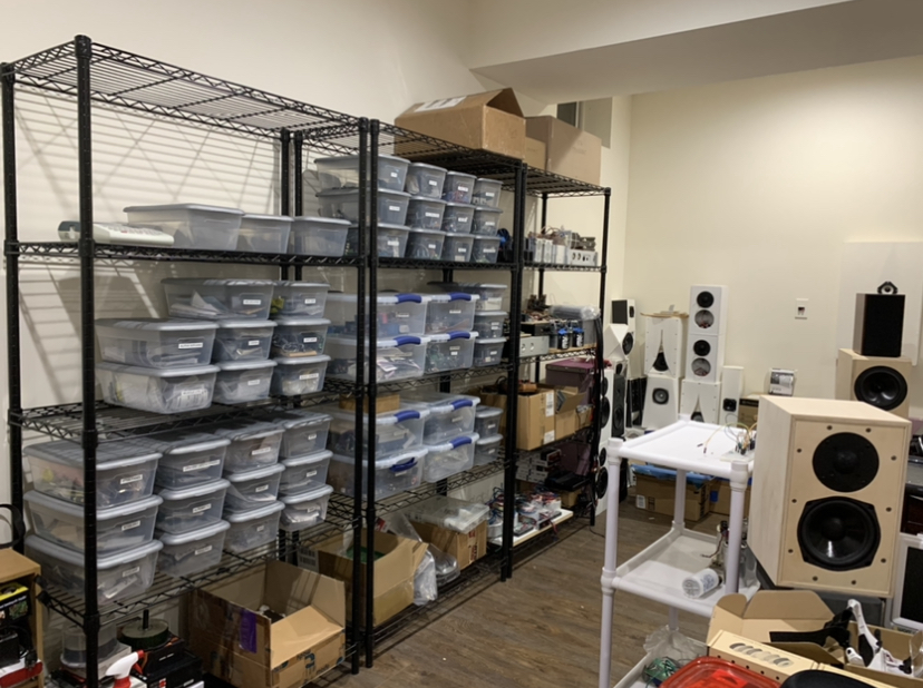
I recently cleaned my lab and bench. It got to a point where I couldn’t find anything and had to take a full day to clean. I bought 3 new shelves and a bunch of storage bins. That made a huge difference. Each little container contains a project BOM and parts. With 4 levels per shelf and each shelf stacked with 12 x 3 total shelves, I can technically hold 144 bins! 🙂
My camera is iPhone XR and lighting is overhead recessed flood light bulbs fitted with 60w equivalent LED bulbs 5200K color temp.
I recently cleaned my lab and bench. It got to a point where I couldn’t find anything and had to take a full day to clean. I bought 3 new shelves and a bunch of storage bins. That made a huge difference. Each little container contains a project BOM and parts. With 4 levels per shelf and each shelf stacked with 12 x 3 total shelves, I can technically hold 144 bins! 🙂
Attachments

Last edited:
I use a basic resistive coiled element “dorm room” single burner stove and an old non stick aluminum frypan/skillet.
Here is a video I made a few years ago of the hot plate / skillet SMT solder paste reflow of my PCA headphone amp boards.
SMT Reflow with Hotplate - YouTube
Here is a video I made a few years ago of the hot plate / skillet SMT solder paste reflow of my PCA headphone amp boards.
SMT Reflow with Hotplate - YouTube
I thought it would be interesting to have a thread where I could talk about what’s OBT (on the bench tonight) - or what do I have to work on. A good chance to show what sort of projects and stuff I am working on.
I also invite folks to post their stuff here if they want - especially if it involves stuff from my shop!
I know there are folks working on FH9HVX, Alpha Nirvana, SLBs, SFPs, Aksa Lender’s, Yarra’s, and Rockville speakers, 10F/RS225 TL speakers, foam core builds, etc. please share what you are working on Tonight!
To kick it off, here is what I will be doing: some SMT reflow soldering of the LU1014D power JFET (I think it is a SIT) TO-247 IMS adapter boards. These will be a test batch to check to make sure they work. There is a GB here - I won’t be running it and the boards can be ordered by anyone as the Gerbers are posted free for all to use.
Woofertester has sent me a batch of matched LU1014D’s to install on these boards. These aluminum substrate boards will allow these peculiar power JFETs to be mounted in an underhung fashion like a conventional TO-247 MOSFET. They should be much easier to use. Also, Nelson Pass is giving away a bag of these unobtanium SITs to they DIYA community. Woofertester is doing the matching and WG45 is handling the GB. Thanks to JPS64 for the awesome layout of this metal substrate adapter board. Thanks to Nelson Pass and Woofertester for the LU1014D’s, and thanks to WG45 for handling the GB that is off to a roaring great start. I can’t believe we have 101 pairs of these adapter boards on the interest list already!
So that’s What’s OBT for me.
What’s OBT for you guys? 🙂
Hey, just saw you had this link over on the Purifi thread. Good idea, will definitely be checking this space

OBT for me is carbon dome tweeter concept dev. Can carbon come in lighter then the BlieSMa's ultralightweight .28g? I'll try and find out...
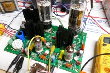
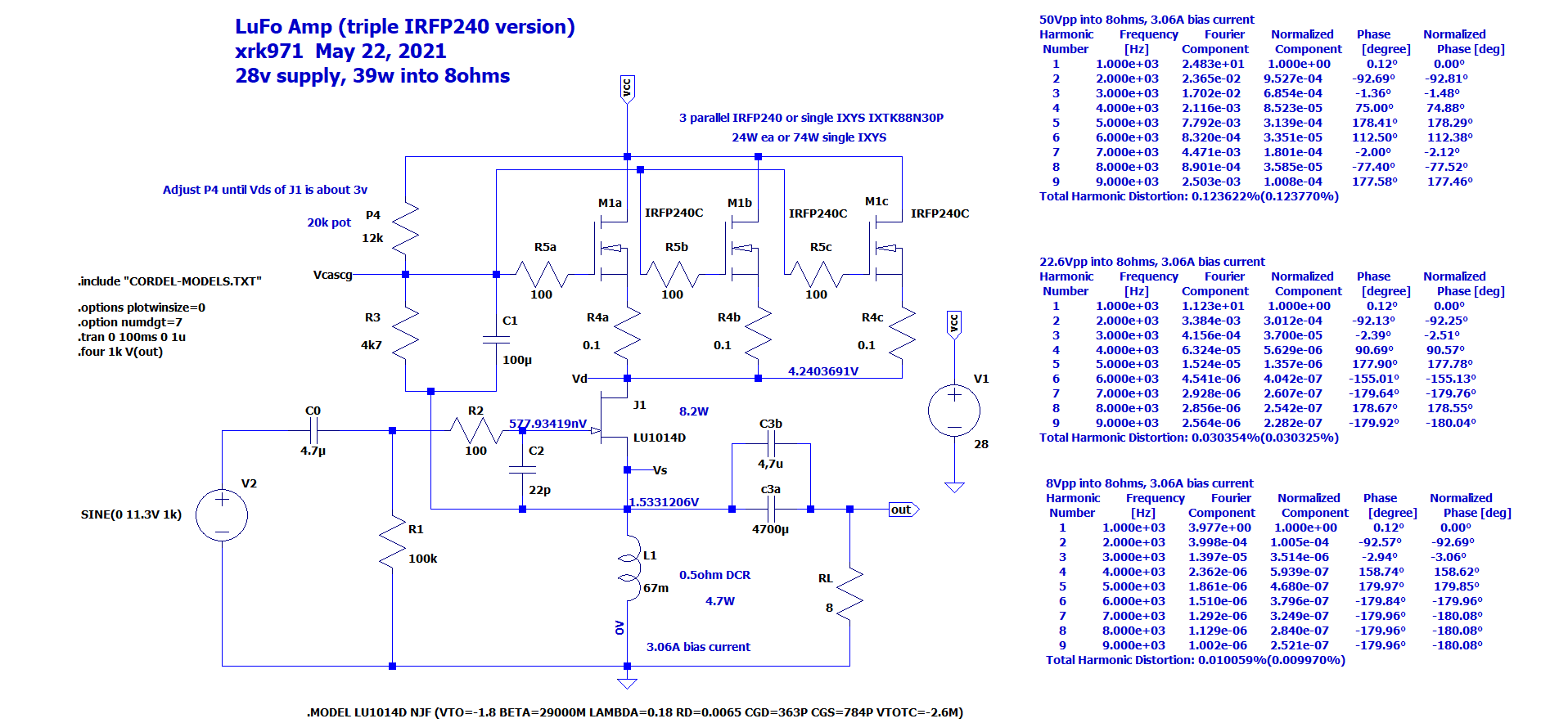
WOBT - May 21-22, 2021 - The LuFo Amp. This is a SE Class A amp using the LU1014D part discussed above with a MOSFET cascode above and an inductive load below to make a 39w amp from 28v of single rail power supply. The proof of concept below used a CPU cooler and fan but it was designed with a conventional passive heatink in mind, hence the use of 3x MOSFETs to spread the heat into 25w maxium dissipation per device so that it can be spread out on a passive heatsink.

Last edited:
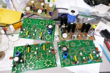
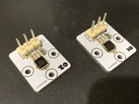
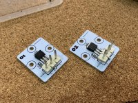
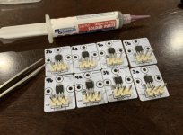
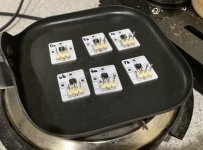
WOBT May 23, 2021: reflow soldering a batch of 16 of the matched LU1014Ds onto IMS TO-247 adapter PCBs. These are for Woofertester.
Applied paste and then place components in place. The LU1014D required bending the legs with a Z shape to get it to sit flush. Total pain to do. Get the LD1014Ds next time:

Here they are getting cooked on a hot plate:

Here they are getting cooled on a wet towel:

Here is a video of me cooking them on my hot plate and also going over them with some hot air:
Reflow soldering LU1014D?s onto aluminum IMS TO247 adapter boards - YouTube
After making them, I checked each one with a transistor tester just to make sure it’s still alive as a n chan JFET.
Applied paste and then place components in place. The LU1014D required bending the legs with a Z shape to get it to sit flush. Total pain to do. Get the LD1014Ds next time:
Here they are getting cooked on a hot plate:
Here they are getting cooled on a wet towel:
Here is a video of me cooking them on my hot plate and also going over them with some hot air:
Reflow soldering LU1014D?s onto aluminum IMS TO247 adapter boards - YouTube
After making them, I checked each one with a transistor tester just to make sure it’s still alive as a n chan JFET.
Attachments

Last edited:
BTSB with Valve Buffer! Sounds delicious. 🙂

Balanced or SE input, SE Triode (SET) valve buffer stage, 0/6/14/20dB gain select, valve buffer bypass switch, balanced and SE output, 0.002% THD, sounds amazing. Only requires +12v input from a wall wart all on board DCDC for +6.3v filament heater, 90v B+, +/15v power supplies.
This is an OEM design for a commercial customer so sorry, not available in my shop.
Attachments
For the LU1014D’a they get warm so I use Sn63/Pb37 no clean solder paste from MG Chemicals. It melts at 186C I think.
MG Chemicals - 4860P-35G 4860P 63/37 No Clean, Leaded Solder Paste, 35 g (1.2 oz) Pneumatic Dispenser (Complete with Plunger & Dispensing Tip) https://www.amazon.com/dp/B00M1RC0Y...abc_A7ZE5W74WB91D61T7V99?_encoding=UTF8&psc=1
For the smaller low power stuff I use low temp no lead paste that melts at 138C. Chip Quick no clean Sn42/Bi57.6/Ag0.4. It reduces the temp that components get subjected to.
Solder Paste Sn42/Bi57.6/Ag0.4 No-Clean Lead-Free Low Temperature Melts 138C 281F https://www.amazon.com/dp/B0195V1QE...abc_K0VFG7JNDXEWM7EQ7RY7?_encoding=UTF8&psc=1
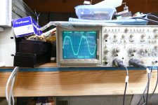
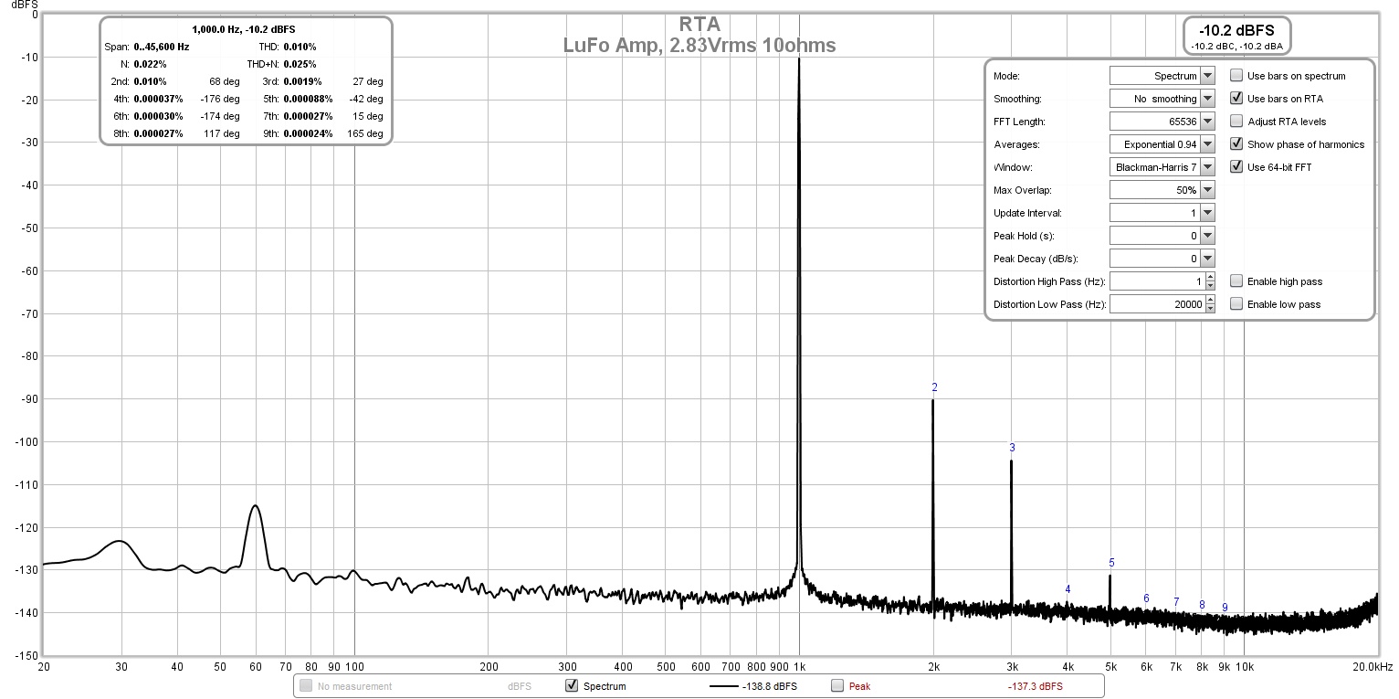
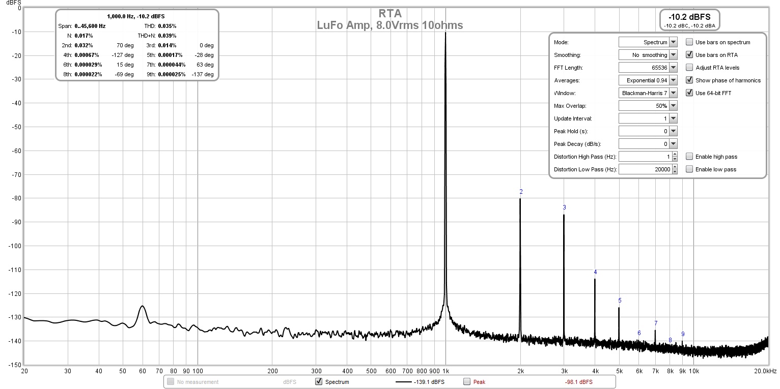
WOBT May 24, 2021: Measurements of LuFo amp.
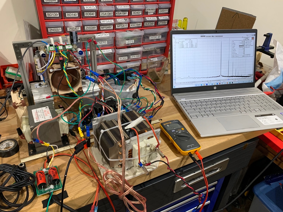
It’s a superb sounding and excellent measuring amp. Very nice harmonic profile. Matches simulation almost perfectly.
2.83Vrms into 10ohms:
8.0Vrms into 8ohms. Still lovely looking profile:
It’s a superb sounding and excellent measuring amp. Very nice harmonic profile. Matches simulation almost perfectly.
2.83Vrms into 10ohms:
8.0Vrms into 8ohms. Still lovely looking profile:
Just discovered your Marketplace !! just ridiculous amounts of goodness. 🙂
do you have a link to more info on the Tubed BTSB?
..dB
do you have a link to more info on the Tubed BTSB?
..dB
And I thought I was the only one crazy enough to literally "cook up" some SMD boards in a frying pan. I used a similar pan on a $15 "Aroma" brand hot plate that I got from Amazon.
I was advised that the fumes coming from overheated Teflon are quite toxic, so I switched to a piece of 0.100 inch thick aluminum held in a pair of Vise Grips. I think it works better since it is flatter. As soon as the solder reflows I move the aluminum from the hot plate to a large heat sink for cooling. I will be cooking up some SMD modules for my Eurorack synthesizer in the near future.
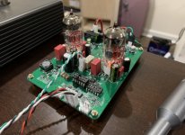
For now, a new UNSET SE tube amp board is on the test bench, and a few more are on the build bench. These use all through hole parts.
The UNSET is a new SE tube amp design, and this one is making 30 watts at 2.5% THD, and 60 very distorted watts when driven about 10 dB harder.
UNSET is coming?
I was advised that the fumes coming from overheated Teflon are quite toxic, so I switched to a piece of 0.100 inch thick aluminum held in a pair of Vise Grips. I think it works better since it is flatter. As soon as the solder reflows I move the aluminum from the hot plate to a large heat sink for cooling. I will be cooking up some SMD modules for my Eurorack synthesizer in the near future.
For now, a new UNSET SE tube amp board is on the test bench, and a few more are on the build bench. These use all through hole parts.
The UNSET is a new SE tube amp design, and this one is making 30 watts at 2.5% THD, and 60 very distorted watts when driven about 10 dB harder.
UNSET is coming?