Out of contention came a suggestion. An argument in another one of my threads here brought the Schitt Magni 3 headphone amp to my attention. The thing is only $99 at Schitt's web site, and it boasts some decent specs.
I intend to get one as a data point for a low cost headphone amp, also to see if I like the way it sounds. I plan to pop the hood when I get the amp, but in the meantime, I can speculate on what's inside based on their posted description and specs, realizing also that there can't be all that much in the box for just 99 bucks. That line of thought has led me to several simulated designs that I'll present in this thread, some better than others.
First off, the amp is described as all discrete bipolar, current feedback, with total DC path from input to output, and a servo to correct offset.
As time permits, I'll post several design simulations with distortion that I have arrived at over the past couple of days. Some fit all the criteria in the product description, some do not. Some designs (esp a couple of early attempts) have flaws that may make them not worth building, but will be presented anyway as part of the learning experience. One of these designs may duplicate what's in the box - then again, maybe not. More later.
No "argument" here on my part.🙄
Glad you're purchasing a Magni 3. If there are any "B-Stock" units left, you'll save about $20.
You're welcome to draw all the negative initial conclusions you want about the Magni judging it by price, its 14VAC adapter, not much "in the box", etc..
While you've got your credit card out, why not go ahead and purchase an Asgard 3 and really hear so good ole' Class A gooooodness...yummy.🙂
I own both as well as the Jotunheim.
Should you think your design sounds better, when it's tweaked as far as you can tweak it, than either of the commercial offerings above, then I'll be glad to PM you my address and pay the shipping both ways just to listen to it.
Who knows? Your design may sound better.
I'll tell you upfront that I DON'T care if an amplifier uses 10 components or 100 components, nor do I care about how well an amplifier "measures".
So posting "simulations" may be meaningful to you or to other people here who'll be following this thread, but they mean nada to me.
For me, it's ALL about the sound and NOTHING else.
Best of luck with improving your design(s) and comparing them to some commercial offerings.
Last edited:
The main impetus for purchasing the Magni box is to see what's in there for $99 and what it sounds like. Don't burden me with assumptions I haven't made, BTW...
I use simulations as a guide to determine whether a given topology might be worth building. Also, since the Magni apparently measures well, I would like to home in on a design that at least is in the ball park, as an exercise.
Having said that, I tend to favor a simple design that listens well, hence the vacuum tube experiments - those might not be the ultimate in measurements, but they beguiled ~50% of listeners at the latest Burning Amp (that was even with output transformers that did not precisely thrill me measurement-wise). If I wanted to go measurement-crazy, I could just use a boosted opamp design with something like an OPA627. What's the fun in that?
I looked at a fair number of current feedback designs in simulation, and one of the things that troubled me in the first couple of tries was the presence of odd-order harmonics (right up to the 7th) not far down from the 2nd, even though the THD was low. A lot of the subsequent effort was to pare down the odd order content. I succeeded in that effort in simulation.
Both you know and I know that simulation is one thing, and the real deal is another. I may not get to actually realizing some/any of the designs presented in this thread for a while, as I have 2-3 other discrete designs that need to be built, boxed, and auditioned. What I have done in those cases is to use a single channel for optimization of compensation using the gain-phase analyzer at my work place. The next step is to put together another channel and box it up for listening tests. Those projects are presented in this section, and are fairly simple designs that measure well in simulation. Again - the real test is listening, and they will get their turn.
So, for the time being, what I present here will be simulations. People can look at them and perhaps use them as a guide to a project that might be worth realizing, or just view them as an exercise - don't care either way. It's my time in question, and my leaning experience.
Last edited:
I have a Magni3 here, a B-stock $79. Which had a scratchy pot and was replaced by a new one immediately by Schitt. Great customer service.
I have several head amps here and have tested against all of them and the Magni3 works as well if not better in some respects compared to some of them.
Its kind of like the O2 explosion back a few years with much less controversy and fanfare. Its a real "sleeper" of an amp IMO.
Measurements are great a good baseline, but over the years it is the "sound" for sure...but your experiments and sims might help correlate measurements to this elusive "sound" we all strive for..
Alex
Attachments
It may be too much to ask, but a look under the hood of your Magni would be appreciated.
I'm going to start posting some circuits and simulation results tomorrow.Going back and looking at the early designs in the series, I found ways to clean things up, so I have fewer misgivings about the early efforts re harmonic distribution, even if the designs are not entirely in line with the description for the Magni amp as posted by Schitt on their web site.
If nothing else, the progression of designs makes for an interesting menagerie.

Thanks- there's not all that much under the hood. I suspect the topollogy is similar to the last of the simulations I'll be putting up, but with a different suite of devices.
Looks like 8 active devices, 2 bias diodes, and an opamp for the servo. As I suspected, it's surface mount, using the PCB copper for a heat sink. I didn't suspect they'd use D2pack devices at the outputs, though.
It also looks like they're using the AC wall wart in a voltage doubler configuration to generate the plus and minus rails - a cost-effective approach.
Last edited:
I have several head amps here and have tested against all of them and the Magni3 works as well if not better in some respects compared to some of them.
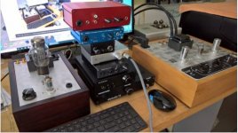
That's quite the collection.🙂
jeff
Ha!
Yes way too much $$$ and time spent on this stuff!! Well...not!!!
After reading so many "opinions" often over hyped and the only way to really tell how something works.."sounds" etc is to have them in house and listen in a controlled environment. Couple that with a love of building stuff, being a tech for 40 years its just satisfying foe me to build stuff and compare to retail high dollar stuff....
More often the not so good looking DIY stuff performs as well as the nicer looking retail stuff....
There are so many much more talented folks here at DIY that share their designs and help us build stuff thats really neat!!
Alwyas room for more stuff!!
Alex
Here's the first circuit with simulation results.
As a "what's in the box" candidate, it fails on the "DC path from input to output" criterion, with input coupling capacitors needed for the input bias scheme to work. It is all bipolar, however.
After giving the circuit a second look and some sprucing up, one of my main objections to it melted away. The initial simulations showed odd order harmonics that stuck around at more or less constant amplitude, After some sprucing up, the harmonic structure looks a lot better.
The devices used were my choice for workhorse components that were available in the PSpice library. The Darlingtons used in the output stage are available as SOT-223 devices (PZTA14, PZTA64) that should be capable of dissipating a watt or so with some decent PCB copper area. I have found that the overall distortion is better using Darlingtons as outputs rather than regular BJTs, possibly due to reduced loading on the preceding VAS .
From the PCB view shown previously, I believe that the output devices used by Schitt are straight BJTs, judging from the number of biasing diodes used. When I get to a circuit that (I believe) is more like the one Schitt actually uses, I may examine the effect of output devices on the on the THD and harmonic profile.
The input drive level was chosen for an output of 1W RMS into 32 ohms, which is the criterion Schitt uses for THD rating.
Keep in mind that these are simulations only, useful for sorting out the relative merits of various circuits, but no substitute for building, testing, and listening.
Attachments
This is a circuit I generated to try and sort out the harmonic content issues posed by the early version of the first circuit. It uses a jfet front end, violating the "all bipolar" criterion of the Schitt circuit. Distortion is higher than in the first example, but still not shabby, and harmonic content looks ok.
I used an input capacitor, but it is not necessary for proper circuit operation. However, I would normally insist on input cap, as I don't trust outside-world sources.
I used an input capacitor, but it is not necessary for proper circuit operation. However, I would normally insist on input cap, as I don't trust outside-world sources.
Attachments
Last edited:
This next circuit is more in line with the design criteria stated by Schitt for their Magni 3 headphone amp, being all bipolar, and potentially with an all-DC path from input to output.
I'm pretty sure that Schitt just uses resistors instead of current sources to bias their input stage in place of current sources I1 and I2, as I see only 8 active devices/side in the picture of their PCB. I use the current sources to increase power supply immunity, and would implement them in practice using a couple of current mirrors and a master current source.
I chose to use all Darlingtons from stem to stern, to reduce the number of line items on the BOM. I also have reels of both the SOT-23 and SOT-223 versions of MPSA14 and MPSA64, another motivation.
I used a couple of tricks that Schitt probably doesn't use in their circuit. The VAS stage transistors use strings of GaP green LEDs for emitter bias (voltage drop without a lot of degeneration resistance). These are represented by V7/R10 and V8/R8. They allow me to increase the value of load resistor on the previous stage for more open loop gain.
I also use a GaP green LED to bias the output stage (V6).
Circuit and simulation results are shown for guidance only. THD is not shabby, and harmonic content looks ok.
Attachments
Last edited:
The last circuit illustrates my love affair with current mirrors. In a real implementation of this circuit, I would use another pair of current mirrors to bias the input Darlingttons.
THD is a little higher than in the previous example, perhaps due to lower open loop gain. Also the high order harmonic content is a little higher than I would like. This might be fixable with a little more effort. Still, this menagerie is not a bad haul for three days of off-and-on diddling with PSpice.
THD is a little higher than in the previous example, perhaps due to lower open loop gain. Also the high order harmonic content is a little higher than I would like. This might be fixable with a little more effort. Still, this menagerie is not a bad haul for three days of off-and-on diddling with PSpice.
Attachments
I'm confused, you have distortions of 0.001% or thereabouts, why does the harmonic profile/structure matter, they are all extremely low, its basically linear for all possible purposes?
None of these circuits have a whole lot of open loop gain, so distortion will rise with input excitation. The specified 1V RMS into 32 ohms is only a little more than 30 mW output.
I want to see a distortion spectrum dominated by 2nd harmonic, with higher odd-order harmonics diminishing with order. I get antsy when I see something like a 7th harmonic nearly as high as the 2nd, even if the THD is low. Higher excitation levels will bring up everything, and may result in listening fatigue. I ran into a situation like that this weekend with a simulation, (2nd and 7th almost equal in amplitude) though I suspect part of the issue is using a version of PSpice at home a lot older than the version I have at work.
I want to see a distortion spectrum dominated by 2nd harmonic, with higher odd-order harmonics diminishing with order. I get antsy when I see something like a 7th harmonic nearly as high as the 2nd, even if the THD is low. Higher excitation levels will bring up everything, and may result in listening fatigue. I ran into a situation like that this weekend with a simulation, (2nd and 7th almost equal in amplitude) though I suspect part of the issue is using a version of PSpice at home a lot older than the version I have at work.
Here is a stripped down version of one of the circuits resented previously, with only 8 transistors, just like the Magni. I'm using LED bias tricks described previously to bias the output and VAS stages. THD and harmonic balance look respectable. I may end up building this one once I figure out the optimum placement for the servo.
I suspect the topology is very similar to the Magni, except for the LED tricks.
I suspect the topology is very similar to the Magni, except for the LED tricks.
Attachments
I've had an entertaining time in PSpice stabilizing this design, as current feedback amps are different when it comes to compensation. I'll re-post the design when I'm finished. It will be interesting to see if the compensation on the real-life amp turns out the same as the simulation. It's different a lot of the time.
Here's the circuit of post 16 tweaked for frequency response. The simulation shows a fast, optimally damped response. I suspect things will look different when I actually build this one up, as the compensation in real life rarely matches that of the simulation, due to strays in real construction, as well as model vs. reality...
Attachments
Last edited:
Don't consider this the final take. I'll be doing some massaging of the design to optimize both THD and bandwidth/stability. The design currently crosses over at ~40 MHz according to PSpice, with no funny business on the way down.
Increasing the feedback network resistance to optimize stability caused an increase in THD. I managed to wrestle THD back down to the ~0.001% region, but it's not as nice as what I started with. Also, there is offset at the input that will require use of an input coupling cap. As always, food for thought and grounds for further research.
Increasing the feedback network resistance to optimize stability caused an increase in THD. I managed to wrestle THD back down to the ~0.001% region, but it's not as nice as what I started with. Also, there is offset at the input that will require use of an input coupling cap. As always, food for thought and grounds for further research.
Last edited:
Why not simulate at a higher level then?None of these circuits have a whole lot of open loop gain, so distortion will rise with input excitation. The specified 1V RMS into 32 ohms is only a little more than 30 mW output.
I want to see a distortion spectrum dominated by 2nd harmonic, with higher odd-order harmonics diminishing with order. I get antsy when I see something like a 7th harmonic nearly as high as the 2nd, even if the THD is low.
I prefer to see all the harmonics in the noise floor, then it doesn't matter, and that's not impossible to achieve.
You can use a weighted sum of harmonics to get a final figure that better represents the thing you want to minimize.
Looking at the distortion residual is a very powerful technique for telling you what's happening too.
- Home
- Amplifiers
- Headphone Systems
- What's in the box?