Hello,
I popped open a tube amp of mine to take digital shots to use for my summer project.
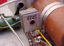
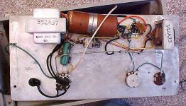
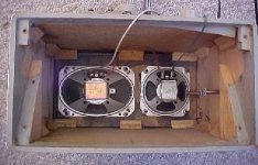
There is one type of component that I am not familiar with. It is the metal, square shaped thing pictured below.
This is placed in between the power source and the tube.
Any clue? What does it do?
Thanks in advance.
Darren
I popped open a tube amp of mine to take digital shots to use for my summer project.
There is one type of component that I am not familiar with. It is the metal, square shaped thing pictured below.
This is placed in between the power source and the tube.
Any clue? What does it do?
Thanks in advance.
Darren
Attachments
Must be 1959-early 1960s.
It is an amp with an ECL82 tube in it.
What would this specific rectifyer do?
Darren
It is an amp with an ECL82 tube in it.
What would this specific rectifyer do?
Darren
That is definitely a selenium rectifier. As I recall, they had a forward voltage drop of 1.4v. They have been replaced by silicon diodes.
Hello,
Thanks for the info.
As part of this project I want to replace all the parts that are not good. Capacitors have to go.
Should I replace this component with a new one or should it be okay?
Darren
(who knows nothing about recitfyers)
Thanks for the info.
As part of this project I want to replace all the parts that are not good. Capacitors have to go.
Should I replace this component with a new one or should it be okay?
Darren
(who knows nothing about recitfyers)
darren01 said:Should I replace this component with a new one or should it be okay?
Most assuridly yes... if it is just a single (half-wave rectifier)you probably want to replace it with a bridge (full-wave rectifier ie 4 x IN4007 would do)
It will have less noise & hum, and you will avoid the not that all uncommon phenomenom of the selinium rectifier depositing its guts all thru-out your amplifier.
dave
the 1n4007 and another part
Thanks for your answer.
You said "full-wave rectifier ie 4 x IN4007 would do."
Do I put 4 of these in series in place of the original?
I see Digikey.com has many types of 1n4007. Which is the best to get?
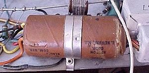
Here is another part I have questions about.
It appears to be a four-in-one type of capacitor. Picture is down below.
Two out of the 5 leads go directly to the tube, one goes to ground, one to the rectifyer, and one to a resistor > tube.
It is a 60-60/40/25 mf capacitor with voltage values are 250-250/200/25.
Do I replace this capacitors with 4 equivalent Electrolytics?
Darren
Thanks for your answer.
You said "full-wave rectifier ie 4 x IN4007 would do."
Do I put 4 of these in series in place of the original?
I see Digikey.com has many types of 1n4007. Which is the best to get?
Here is another part I have questions about.
It appears to be a four-in-one type of capacitor. Picture is down below.
Two out of the 5 leads go directly to the tube, one goes to ground, one to the rectifyer, and one to a resistor > tube.
It is a 60-60/40/25 mf capacitor with voltage values are 250-250/200/25.
Do I replace this capacitors with 4 equivalent Electrolytics?
Darren
Attachments
Re: the 1n4007 and another part
Here is an article i did on a simplier, but similar amp with scematic & pictures, look at the power supply
http://www.t-linespeakers.org/tubes/SEP_50EH5.html
Yes, althou there are some places where you can get multipart elcos for restoration purposes.
Before you do anything you want to trace out the circuit (this is a very valuable learning experience)
this site will be helpful
http://tdsl.duncanamps.com/tubesearch.php

dave
darren01 said:You said "full-wave rectifier ie 4 x IN4007 would do."
Do I put 4 of these in series in place of the original?
Here is an article i did on a simplier, but similar amp with scematic & pictures, look at the power supply
http://www.t-linespeakers.org/tubes/SEP_50EH5.html
It is a 60-60/40/25 mf capacitor with voltage values are 250-250/200/25.
Do I replace this capacitors with 4 equivalent Electrolytics?
Yes, althou there are some places where you can get multipart elcos for restoration purposes.
Before you do anything you want to trace out the circuit (this is a very valuable learning experience)
this site will be helpful
http://tdsl.duncanamps.com/tubesearch.php
dave
this scematic of Morse's 6BM8 amp (there is a whole thread on it) will be roughly the same as yours (at least in terms of where things should be -- values may be different -- your amp may well have a bypass cap in the cathode of the pentode)
dave
dave
Attachments
Re: Re: the 1n4007 and another part
Hello,
Thanks, again for the replys. You are very helpful.
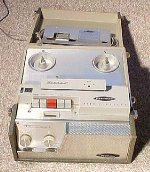
This isn't a restoration job. I am aiming to bring this stylish 40+ year old tube amp'ed Stereo Reel to Reel Hi-Fi system up to date.
It isn't worth more then $10 as it is. Other RtR recorders from the same era and by the same manufacturer rarely sell on eBay even when listed at $5.
Very heavy. Postage is more than the value of these things, I recon.
I tried it just now and am no good at it. I am much better at point-to-point removal and replacement soldering.
Show me a scematic and I am lost. Show me the physical finished product and I understand it.
Thanks for the tips and hints.
As stated above, I just want to bring this up to date as much as I can for the fun of it.
I got some old reel to reels. Hours worth. It would be great to be able to listen to them in better quality or even record over them in stereo.
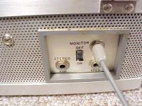
Taking all the old capacitors out and replacing them with good audio grade or better one, replacing the recitfier and putting new plugs and jacks on it is the mission.
Basically, I am hoping for something that sounded better when bought new.
I will be posting at DIYaudio.com very often as I find the parts and progress is made.
There will also be a website. I have over 40 photos taken for it already.
Back to the rectifier thing. Do I solder all four of these in series?
Can someone show me an example of how this is done? I am ordering those parts, along with others, tomorrow afternoon.
Darren
planet10 said:
Yes, althou there are some places where you can get multipart elcos for restoration purposes.
Hello,
Thanks, again for the replys. You are very helpful.
This isn't a restoration job. I am aiming to bring this stylish 40+ year old tube amp'ed Stereo Reel to Reel Hi-Fi system up to date.
It isn't worth more then $10 as it is. Other RtR recorders from the same era and by the same manufacturer rarely sell on eBay even when listed at $5.
Very heavy. Postage is more than the value of these things, I recon.
planet10 said:
Before you do anything you want to trace out the circuit (this is a very valuable learning experience)
I tried it just now and am no good at it. I am much better at point-to-point removal and replacement soldering.
Show me a scematic and I am lost. Show me the physical finished product and I understand it.
planet10 said:
Thanks for the tips and hints.
As stated above, I just want to bring this up to date as much as I can for the fun of it.
I got some old reel to reels. Hours worth. It would be great to be able to listen to them in better quality or even record over them in stereo.
Taking all the old capacitors out and replacing them with good audio grade or better one, replacing the recitfier and putting new plugs and jacks on it is the mission.
Basically, I am hoping for something that sounded better when bought new.
I will be posting at DIYaudio.com very often as I find the parts and progress is made.
There will also be a website. I have over 40 photos taken for it already.
Back to the rectifier thing. Do I solder all four of these in series?
Can someone show me an example of how this is done? I am ordering those parts, along with others, tomorrow afternoon.
Darren
Attachments
Re: Re: Re: the 1n4007 and another part
You'll need to learn to read schematics... they are the language for describing circuits...
Here is how you wire the rectifiers (each one has a band at one end -- correcsponds to the bar on the diode's symbol)
dave
darren01 said:Back to the rectifier thing. Do I solder all four of these in series?
You'll need to learn to read schematics... they are the language for describing circuits...
Here is how you wire the rectifiers (each one has a band at one end -- correcsponds to the bar on the diode's symbol)
dave
Attachments
How many connections are there to the selenium rectifier? (Some have two, some have three, others have 4). Which connections go to the power transformer, earth (ground) or capacitor positive terminal?
Even a rough drawing may be helpful.
Cheers
Even a rough drawing may be helpful.
Cheers
planet10 said:
Dot a close up of the speaker?
dave
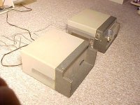
Hello,
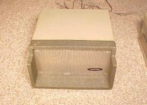
This is quite a interesting tape machine. The Hi-Fi system comes in two parts; recorder/speaker and external speaker.
There are cones inside the recorder that are amped. They serve as the left channel.
On the back there is a line output that connects to the other amp which amplify's the right channel.
The circuit that I want to start with first is this external right channel amp. It is the one that I took the inside photos of that are shown above.
Darren
Attachments
Centauri said:How many connections are there to the selenium rectifier? (Some have two, some have three, others have 4). Which connections go to the power transformer, earth (ground) or capacitor positive terminal?
Even a rough drawing may be helpful.
Cheers
Hello,
I am puttiing the project on hold until the IN4007 parts arrive.
Should be a week from now or sooner.
The old rectifier has two connection points, as shown in the scan at the top of this thread.
I'll draw something up later but it exists between the first transformer and the tube.
Here is the lineage
Transformer > recitifier > resistor > pin 7 of the tube.
BTW, I just ordered some of the recitifiers. 1N4007 made by Fairchild Semiconductor. Can't beat the price. $.05 each.
I hope these are the right ones. If not, it is no great ammount of money lost.
BTW, the attached image is of the entire circuit that I am working with. Not very complicated lookin at all.
Darren
Attachments
planet10 said:
Dot a close up of the speaker?
dave
Hello,
The speakers in the recorder are under the grill. I can't take a snap shot of them until I take the recorder apart.
However, here are what the speakers look like in the right channel amp.
Darren
Attachments
darren01 said:Transformer > recitifier > resistor > pin 7 of the tube.
There should be a cap connected to the rectifier going to ground as well...
dave
planet10 said:
There should be a cap connected to the rectifier going to ground as well...
Yea, two. I think they are the 60mf caps.
I didn't list them. I just listed the stuff that is in direct line of the transformer > rectifier > tube
When I get the 1n4007s I will try to draw something out.
I plan to make a new thread on the recorder project. It will be posted here and possibly tapeop.com. A nice DIY website will be included. 🙂
BTW, I am going to do the recorder project in phases because there are several key things that I want to do to improve it; make two channel stereo line output, make a better mic preamp, make it a stereo mic preamp (currently it is mono. go figure), install a stereo recording head, and possibly a new playback head.
A really nice recorder that will make a great summer project for me.
A lot of the new parts are about $5 and under. Easy on the pockets. 🙂
Darren
- Status
- Not open for further replies.
- Home
- Design & Build
- Parts
- What type of part is this? My amp project :)