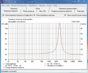
I am new to designing crossovers.I downloaded xsim, and am currently playing with a downloaded frd and zma file for the scanspeak d3004-6600.
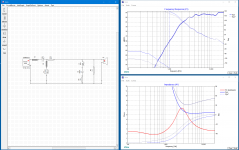
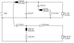
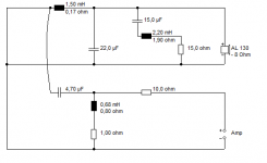
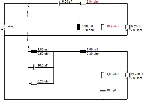
Starting point was a crossover from Troels Graveson (screenshot attached). I was wondering why he did what he did, and played around with the components.
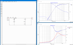
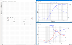
It turns out that it was quite easy to manipulate component values, adn topology too, without significantly changing the frequency response. This is unsettling since it means that manipulating the FR to a desired shape may lead to many, more or less, identical solutions.
I have also been looking at other parameters such as system phase, system impedance and also lookback impedance, but I don't see anything more desirable between the 3 solutions.
So, my question is, how do you know the when filter is optimal. What should I be looking for. Is there a good book on this?
P.S.
I am a beginner in speaker design, but still an EE with sufficient knowledge of the basics. My goal is to acquire measurement capabilities and develop competences to design high end crossovers.
I think I need more advanced input than what I normally find on the internet.
Starting point was a crossover from Troels Graveson (screenshot attached). I was wondering why he did what he did, and played around with the components.
It turns out that it was quite easy to manipulate component values, adn topology too, without significantly changing the frequency response. This is unsettling since it means that manipulating the FR to a desired shape may lead to many, more or less, identical solutions.
I have also been looking at other parameters such as system phase, system impedance and also lookback impedance, but I don't see anything more desirable between the 3 solutions.
So, my question is, how do you know the when filter is optimal. What should I be looking for. Is there a good book on this?
P.S.
I am a beginner in speaker design, but still an EE with sufficient knowledge of the basics. My goal is to acquire measurement capabilities and develop competences to design high end crossovers.
I think I need more advanced input than what I normally find on the internet.
Attachments
You showing us a few passive filtered, high-passed responses of a tweeter. That's one thing and contains some information, but that tweeter needs to be mated at least with a midwoofer. So the individual drivers frequency responses, relative phases, off-axis responses, directivities, distortions, break-ups, combined impedance etc., all needs to considered in for the filtered tweeter response being judged objectively.
Last edited:
The transfer function is the key, and that is to say that the way you filter is not as important as the target, unless it gives your amplifier a difficult load.
Some will begin by looking to get a frequency response plot flat in band and rolled off to a target at the crossover. Ultimately you take more than response into account.
Some will begin by looking to get a frequency response plot flat in band and rolled off to a target at the crossover. Ultimately you take more than response into account.
Can you rely off of just the published specifications of a speaker, Or should you use a calibrated mic and REW to get your numbers to input into the program ?
Hi, yes, drivers have some manufacruring tolerances and the published graphs are often measured with a big baffle and not from an actual speaker box, especially it is not from your speaker box. You can get a speaker to sound nice without measuring or with minimal on axis measurements but don't expect anything stellar. Stellar needs multiple measurements (google spinorama) and good ears as well as time and money to tweak until goal is met. The main thing is to have fun, so anything goes!
ps. I've been slowly tweaking a prototype(s) few years now and finally getting ok sounds from it! Expectations are high though, and I like it as an hobby, having lots of fun out of the journey 🙂
ps. I've been slowly tweaking a prototype(s) few years now and finally getting ok sounds from it! Expectations are high though, and I like it as an hobby, having lots of fun out of the journey 🙂
Last edited:
I think you should use simpler software to learn a bit :
Software | Visaton
Loads of projects of varying quality to try out:
2 Wege – Boxsim Projektdatenbank
You just put them in the projekte folder and they run. Boxsim has an optimiser that lines everything up as flat as it can get it.
The theory:
Some tinkerings of mine:
Restoring Monitor Audio R300 bookshelf speakers.
So, my question is, how do you know the when filter is optimal. What should I be looking for. Is there a good book on this?
It's easy as you've found to hit a target acoustic frequency response curve with one driver. All you really have here is a filter - not a crossover. There is no other driver in the system.
However, assuming you want to build a multiway system - will the phase response match suitably when you pair it with another driver to net you the desired frequency response both on and off axis through the crossover region?
So adding another driver - that's where it gets trickier.
Plus - your source FRD is likely missing baffle / enclosure effects. The 2 key being diffraction ripple (which can be lumpy for your typical 2 way speaker for the tweeter between 1KHz and 3KHz depending on baffle size and tweeter placement) and baffle step - the frequency range where a woofer transitions from 4pi to 2pi radiation with increasing frequency (6dB rise). Without taking account of the latter - you end up with a "bass weak" speaker.
The last point - unnecessary components or values so high / out of range they have no effect. Take your series impedance compensation circuit. 100uF cap and 1mH inductor. I'd garner these are useless. Impedance compensation is really only useful if you must have an even impedance load (low phase swings) for your amplifier OR you are crossing the tweeter near it's resonance frequency (a bad idea anyway) and you need constant impedance for your crossover transfer function to be maintained.
So - remove that impedance compensation and see if there is any impact.
I think I need more advanced input than what I normally find on the internet.
The Internet is a book. All of them. The Loudspeaker Design Cookbook by Dickason is the usual reference cited. Don't bother with Murphy's intro book nor Weems Designing, building and testing books (not enough useful content). speaker building 201 by Alden may be useful (I do not have / have not read). Testing loudspeakers by Joe D'Appolito is often quoted too.
Thanks for so many useful responses.
What was mentioned a few times turned out to be true: I also added a woofer, and, indeed, even though the FR for the tweeter is identical for every variation of the high pass, the crossover to the woofer was different for each version. This hadn't yet occurred to me (seems very obvious in hindsight, but learning often works like this).
So, the take away is to focus on the target curves and optimise the crossover between the drivers. (and make no stupid mistakes like creating super low impedances etc.)
What about look back impedances? In some designs I have looked at, the drivers see a very high impedance at some filter resonant frequency. I would think this is undesirable since there will be no damping of the system.
Thanks for the link to boxsim. Does this software also work with actual FR and impedance measurement data? That's what intrigues me in xsim: in theory the results should be dead on (provided I do my measurement very well, which does NOT seem easy at all).
Of course I will eventually perform measurements on the actual baffles. These should show the baffle step, which I had been aware of. For now I am just playing a little to see if I think I'll be able to pull this of.
The driver doesn't change just because it is connected to a different source impedance.What about look back impedances? In some designs I have looked at, the drivers see a very high impedance at some filter resonant frequency. I would think this is undesirable since there will be no damping of the system.
I am probably one of the few people in the World who know how to calculate back-impedance. An interesting factor in loudspeakers.
I assure you Boxsim can do it:
Software | Visaton
Get to know simple tools and they can lead you to greatness. The main trick is don't make it more difficult than it is. 😀
I assure you Boxsim can do it:
Software | Visaton
Get to know simple tools and they can lead you to greatness. The main trick is don't make it more difficult than it is. 😀
Steve, are you talking about the driver impedance as a result of its own actions, or the source impedance as seen by a crossed driver?
When I use a word like back-impedance, like the Red Queen, it means exactly what I choose it to mean... 😀
But I mean the impedance the driver sees looking back to the amp.
Here what the tweeter sees in a regular metal 5" plus 1" looking back to a voltage amplifier. Surprising, eh? 😎
But I mean the impedance the driver sees looking back to the amp.
Here what the tweeter sees in a regular metal 5" plus 1" looking back to a voltage amplifier. Surprising, eh? 😎
Attachments
Yeah, this is what I meant. Calculating this ain't rocket science me thinks.
So, do we take this into account? My assumption has been that near the peak the driver might not behave as we hope.
So, do we take this into account? My assumption has been that near the peak the driver might not behave as we hope.
I have a fairly open-mind on loudspeakers, and I am not sure source impedance matters much, after all, Harbeth speakers have horrible impedance:
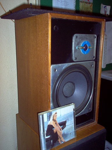
This one sat unloved and unwanted in my local Thrift shop for weeks, £30 is not a bad price. I decided to give it a home.
Absolutely excellent speaker. 😀
Some serious puzzling threw up the answer.
The crossover was way better than most people expect at the price. A work of genius IMO. How he or she got it past the accountants defeats me. 🙂
So now we have mentioned circuit impedance from three positions.. the driver internally, the driver source, and the speaker externally as seen by a Voltage source amplifier. The ensuing conversation would be quite different in each case.I am not sure source impedance matters much, after all, Harbeth speakers have horrible impedance:
Hi Allen,
Yes, the discussion would get somewhat diffuse. My concern has been the impedance that the driver sees on its terminals.
I am not an expert on moving coil systems, but my midrange has a Qm of 13, which means there is very little mechanical damping (if I understand the parameter correctly). Hence, the system (which is at least 2nd order, which we want to bahave as a zero order) would to be relying mostly on electrical damping. At the given frequency, the impedance of the source is very high, and, hence, insufficient damping.
My reasoning may be flawed. As I said: these are my first baby steps in speaker design and I am trying to learn what is of importance.
On a side note:
Another thing that has worried me is the behaviour of a driver that is filtered by only a inductor (say the same midrange). In the frequency range above its resonance frequency (in my case 300 - 800 Hz) the voltage at its terminal is actually higher than the input voltage of the crossover. The effect is probably caused by the capacitive nature of the driver impedance at these frequencies, combined with the inductive filter and very little damping. The effect on the FR is little, but I worry about its transient (time) behaviour.
I have examined other designs and have never seen this effect mentioned. This could mean it is unimportant. (I know I have a tendency to make thingS more difficult than they need to be)
The answer is the same for both questions. Look at the resulting response in relative terms. If there is a resonance per se, it will show up there (with things of this nature anyhow, such as drivers and filters).
I have studied this loudspeaker lark for more years than I care to remember. 😀
IMO, most of the top people know that the original sound we try to reproduce is the sound of real music.
About half of what I know comes from Mr. Lynn Olson:
Nutshell High Fidelity
I have me other little heroes:
SpeakerBuilding.com - Interview with Joachim Gerhard of Audio Physic, Page 1
Robin Marshall: A Modicum of Genius | Stereophile.com
I could mention many more. A hobby, by definition, is an interesting waste of time. But in the end, the satisfaction a speaker gives you is based on how accurate it is. In your room. 🙂
- Home
- Loudspeakers
- Multi-Way
- What to look for when designing a crossover