I am redoing a bunch of the equipment in our "music" room. We have a medium power tube amp or two, but I've decided to redesign the "PA", which was used for bass, keys, guests and vocals (wide response expected for MI amp, I guess). Here are the parts:
-6x 6P3s-E beam tetrodes
-A big 100W Marshall replacement OPT (1900 ohms, tapped for 4,8,16)\
-A handful of 20w OPTs (generally 5k-10k to 8R)
-A huge 1959 organ chassis with 10 octal sockets, and 5 noval, a 40w OPT is already onboard (5k).
-The associated power transformer is very large, core is about 4"x5"x6", provides two B+ windings (I believe one is a tap on the other, however) and 12.6v. I think the transformer powered mucho outboard equipment on the original organ.
-A handful of smaller PTs, various voltages
-A bunch of preamp tubes
-A nice heatsink with two 450v BJTs (2SKsomethingorother) from a computer supply
-A variety of chokes
Any ideas for what kind of design I should pursue? I don't think I can do a circlotron style output, since the one B+ winding is actually taps on the bigger winding. I am thinking that a bipolar supply might be of use, so I can use a direct coupled driver for both sides of a conventional push pull. There's no easy way that I can think of to use the smaller OPTs to drive the power stage, I think. I just read in Radiotron about neon-coupled designs, which I have never seen (possibly noisy?). Anyways, this is just a big parts bin project for sunday afternoon (and probably onward 🙂 ). Ideas much appreciated!
Thanks,
m6tt
I decided on a push-pull parallel, 3x 6p3s-e per side. Cathode bias via 200-ohm resistors each all connected to a 75-ohm 1-amp ceramic rheostat (huge), which should give something like the equivalent of 0-700 ohm adjustable bias. Equal filaments per side of the 12.6 winding, second side of each tube heater connected to ground via cathode resistors (thus biasing cathode with dc and getting 6.3v per tube). Cathodes are fused at 1.5 amp per side. Screen supply is taken from inside B+ taps, not sure if I need to put resistors in like the SVT. Will probably use some form of cathode feedback in addition to slight global feedback.
Haven't quite finished designing the driver, but I intend to drive each side's grid with an IRF820 source follower, driven by a 6CG7 floating paraphrase. That leaves me with 3 noval and 2 octal sockets, probably do a push-pull 6SN7 or SE 6EM7 for the reverb. Outboard chassis with the input jacks etc has two more noval sockets. I do have a NOS 6L7 and some input xfrmrs, so a 50s RCA mic/guitar preamp ain't to far, but probably will end up with something simpler.
Power supply isn't totally designed yet, but I decided against a bipolar supply for many reasons. Plus I prefer cathode bias, it's cold lately 🙂. Solid state rectification is a certainty, into a 680uF bank of computer power supply caps. Hopefully that'll be enough. Got a bunch of 4k7s for the preamp dividers.
Speakers are a mix mash, right now they'll probably be a series-parallel 2x12 + 2x15. If I recall it's something like two Utah 12s, a CTS 15 and a peavey black widow HD.
*eventually* this will be the HF/upper mids driver with an eventually modified Flame linear 700b driving the peavey cab for bass (currently empty). Time for more math to see if I can run it B2. As is, it ought to handle small shows or a rockin' party. Makes a mean boat anchor, in any case...estimated weight is somewhere between 60-80 lbs 🙂.
Last edited:
Alright, so I'm still working on this thing. I had tried and failed to get a 6AV5GA cathode follower to drive each side. So I swapped those for two IRF820 (actually the higher capacitance NTE knock-offs locally available 🙁 ). It amplifies music, but there are some disturbing circuit conditions I can't explain. Total plate supply voltage is 505v. One side's anodes seem to be at 660v. Cathodes are all around 45v. One mosfet seems to drive about 6v higher than the other...oscillation? The OPT is a strange beast, actually 1700CT. Center tap is white, plate leads are red and blue according to manufacturer. DCR is not equal.
I've attached a schematic of the power stage. Comments, criticism, and screaming hate mail welcome:
I've attached a schematic of the power stage. Comments, criticism, and screaming hate mail welcome:
Attachments
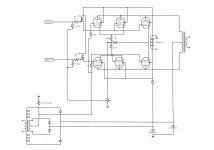
I wanted to make a quick explanation of my understanding of how the biasing works here...First off the power transformer is back biased by a giant 60 ohm resistor mounted to the chassis, near where the fan will be. This gives me a -10v quiescent supply. The power tubes are cathode biased up to 45-50v via the resistor network in the cathodes. The potentiometer (a giant ceramic rheostat from a motor controller) takes a small amount of voltage to provide bias for the mosfets (approximately 10v). The mosfet sources tie to the -10v supply through a 10k resistor. Since they are DC-coupled, the rheostat sets the Vgk by adjusting the amount of V on the mosfet gates. Current conditions are something like 20-30v Vgk after the circuit settles.
I'll be surprised if this doesn't oscillate. You definitely need grid stoppers and you may well need some small inductors in the plate leads to keep things calm.
Will grid stoppers prevent AB2/B2 operation, or just limit the power dissipated in the grid somewhat? How many turns on the plate leads do you recommend? I had plenty of space in this chassis for good lead dress, and all grid wires are shielded or twisted pair, screens and plates are twisted together (that seemed good to me, not sure though). Everything is point to point and "layered" away from each other in 3 dimensions with perpendiculars etc. No AC on plates or screens w/o mosfets, but Vgk is about 40v in that condition.
Audio sounds clear, I am using a heavily used 30w 70v PA head to drive the mosfets during testing. If it's oscillating, it's oscillating very high frequency. I'll try to rig up an RF detector for the mulitmeter and check. Not getting RF burns from the secondary or nearby grounded metal surfaces, at least! There was much less "stray" AC on screens plates etc. before the mosfets were added. I am thinking its the mosfets oscillating, and some screen related oscillations perhaps.
The plate voltages on the side where they read wrong start out at 550v, as current is drawn drop to 495, and then as the tubes turn on ramp up to about 660v. I suppose RF might read as DC to a bad multimeter such as my own.
For a normal-sized grid-stopper, there won't be much of a limit to AB2 or grid current- something like 1-2k is typical. It forms a low pass filter at the input.
The plate inductors are trickier and very much depend on layout. Sometimes, they're just used on the tubes with the shortest leads to the output transformer. A few turns around a 100R 2W carbon comp would probably do it.
The plate inductors are trickier and very much depend on layout. Sometimes, they're just used on the tubes with the shortest leads to the output transformer. A few turns around a 100R 2W carbon comp would probably do it.
Grid stoppers on the side that had incorrect voltages have already fixed the problemo. Hadn't even put in the grid stoppers on the other side yet. Ended up using 1k, since I had 5x 1.5k (one short...). Grounded the shielding on the grid wires between each tube as well instead of just both ends of the bus.
Is there an easy and safe way to make sure both my mosfets are still working? I did my best to limit their exposure to static electricty etc. but I guess I'm paranoid about NTE stuff anyway.
Is there an easy and safe way to make sure both my mosfets are still working? I did my best to limit their exposure to static electricty etc. but I guess I'm paranoid about NTE stuff anyway.
You mean other than simply plugging in some music and listening to it ? This is why I always keep a cheap speaker around and it's still alive 😀 Worst case scenario they are blown and would impose DC on the speaker, which can be measured easily. Put 50/60 Hz audio on the input just in case if your voltmeter doesn't take RMS AC readings so you get more predictable results.
I don't think I have ever used NTE parts but to put your mind at least somewhat at ease: input capacitance of cathode follower isn't all that horrible as there is no Miller capacitance to contend with (actually there is some still, but it is negligible).
I don't think I have ever used NTE parts but to put your mind at least somewhat at ease: input capacitance of cathode follower isn't all that horrible as there is no Miller capacitance to contend with (actually there is some still, but it is negligible).
Well, I plugged in some music. The preamp schematic isn't right, the cathode follower was driving the LTP into grid current. The Vgk was -40, I bypassed all the 250-ohm resistors with 10-ohm. It's now -28 (about spec for AB2 via STC 807 datasheet, -27). I did a quick rearrangement of the values.
The good news is that it is incredibly loud, to the point where I was worrying about the survival of paralleled drivers and neighbors. The bad news is that it was incredibly distorted (imagine standing say a mile from a loud concert distorted). Some transients had a "videogame" sound to them, and some bass notes were fuzzy (feedback might help here eventually). There is also a significant 120-hz hum, which is not really affected by grounding inputs etc. The 2k (10W) divider to the LTP is getting hot and fixing to die. Something just isn't right yet, I think there still may be oscillations or operating point issues. The preamp of course is far from perfect at this point.
I am going to redo the cathode circuits, since there's too much resistance in there. They are also tied to the heaters, and I fear that my hum is cathode driven. Do MOSFETs usually require extreme filtering of the B+? I already have something like 240uF. I will probably also put in anode and screen stoppers while I'm at it, requiring rewiring about half the pins on 6 sockets (ppp is a chore!).
Based on the dB I am getting though, once the sound is clearer, this will certainly be enough power for my application.
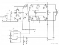
I just removed the back bias supply (1k grid R goes to ground instead of back bias -8), properly bypassed the cathode R and fiddled the preamp to get Vgk right between the voltage stage and the LTP.
It's ALIVE! The preamp is far from optimized (settled on 12AT7 or 12AU7 driving 12AU7 LTP, to be replaced by 6CG7 driving 6CG7 when I redo the heaters) but after putting in a selection of resistors I got Vgk close (+10 on LTP cathode). Haven't redone the loadlines yet even. Clarity is much improved, but I think the preamp could be tons better. In any case, the hum and some weird sonic artifacts have been cleared out by fixing the pre.
No feedback yet, should sound even better (until it clips, of course). I may put another coupling cap at input to roll the ULF off (bass clips much sooner than treble).
Attachments
Last edited:
- Status
- Not open for further replies.
- Home
- Amplifiers
- Tubes / Valves
- What to do with these parts?