I've just stumbled across a few NOS 803's and I'm trying to work out what to do with them. Either way, I'm not going to do anything with them now. I'm just wondering if I hold onto them for the big ol' transmitting tube project sometime down the road, or pension them along to someone else who can use them.
I've done a bit of searching round here and the net in general and not found any info on using them for audio, so I'm wondering if it's possible at all. I scored sockets for these a while ago that I've held onto on the off chance I'd find something to go into them, so I'm safe there.
So anyone know of anything interesting done with these?
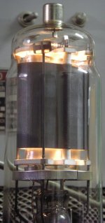
The filaments seem alright 🙂
I've done a bit of searching round here and the net in general and not found any info on using them for audio, so I'm wondering if it's possible at all. I scored sockets for these a while ago that I've held onto on the off chance I'd find something to go into them, so I'm safe there.
So anyone know of anything interesting done with these?
The filaments seem alright 🙂
Attachments
I've got an 803 in my collection. They are comparable to the 813, which has been used in DIY audio power amplifiers, as an Internet search will reveal. I've got four 813 which I hope to use in an amplifier some day.
Melbourne, VIC.
Melbourne, VIC.
That about sums up my thoughts so far also. Seems that if anyone is using them for audio the are keeping quiet about it on the net.
Cheers.
What part of Melbourne are you in?
Cheers.
What part of Melbourne are you in?
I can't tell you what to do with them, but I can tell you what steps I would go through to figure out what to do with them if they were mine.
First I'd grab a data sheet from Frank's Electron Tube Pages. Reading through it I'd note that it's a pentode with a max plate dissipation of 125W.
I would probably want to try it triode strapped. As a first step to determining a good operating point I'd look at the screen ratings: it shows a max Vg2 of 600V. Even though all of the operating points listed are for class B and C they still offer us some clues. Most of them show a screen voltage of 500 to 600 V and a grid bias in the -60 to -100 V range. They show PEAK signal (grid) voltages somewhat higher than the bias voltages. That means they run the tube into grid current, but not much. That's good news because it means that you could probably get some useful power out of the tube without driving the grid positive (compare, for example, to the 810 which needs to be biased positive to start.)
So, just to get started, I would probably make the WAG that it could be run class A1 triode strapped (plate, g2 and g3 all tied together) at around 600V with the grid at around -50 with something like 100 to 150 mA of cathode current. Don't know what kind of load to use. Something fairly high like 10k would probably work. At his relatively low voltage you might get away with something like 5k.
If you can find pentode plate curves taken at multiple screen voltages then you can plot crude triode curves. For each set of curves note the plate current where Va = Vg2. You'll get a separate data point for each grid voltage. Plot all of the data points on a new graph and draw a smooth curve through the points with the same grid voltage. It's easy with Excel, but it's not too hard to draw it by hand.
-- Dave
wow. that just illuminated so much for me. i'd always wondered exactly how to take a tube and a datasheet and figure out voltage/current/load etc. thanks. 😀
I still have a dozen left with good heaters . I asked here and on AA if someone ... almost no responses .  The 803 seems to be happy with 2kV on plate . So
  ... 😕
... 😕
The 803 seems to be happy with 2kV on plate . So ... 😕Hi,
Sorry to burst your bubble, but I think the 803 is bad for audio frequencies because of the very tight pitch of the grid wires of the elements. I have never seen any data sheets for the 803 that recommends them for audio service. Even if they would work, the output transformer would have to have an unbelievably high plate to plate impedance. Maybe I'm wrong but all of these reasons make it a good RF tube though...
Daniel
- Status
- Not open for further replies.
- Home
- Amplifiers
- Tubes / Valves
- What to do with 803's