I am curious as well. Just found the item on eBay. It includes a schematic. At first, I thought: nothing special, but on a second look I saw the 630V B+ (no values given for the resistors though).
https://www.ebay.com/itm/325824326993?hash=item4bdca4ad51:g:I7sAAOSwjF9kyvlS
https://www.ebay.com/itm/325824326993?hash=item4bdca4ad51:g:I7sAAOSwjF9kyvlS
Just found this thread, it appears to be indeed higher voltage, less current and higher impedance on the primary.
https://www.diyaudio.com/community/...mp-with-net-single-bias-trimpot.400962/page-2
https://www.diyaudio.com/community/...mp-with-net-single-bias-trimpot.400962/page-2
The schematics seen in these links all point to designs with a lot of B+ voltage. For any given tube to remain in a safe plate dissipation range, the operating current must be reduced if the plate to cathode voltage is increased. This requires a higher negative bias on the control grid which pushes the tube away from A2 and into A1 operation.
The old textbooks referred to class A as operation where PLATE current flows for all 360 degrees of an audio cycle. This is REQUIRED for a non distorted output in a Single Ended amplifier.
Class A and class AB was further divided into A1 and AB1 where the tube or tubes are operated such that NO control grid current flows at all during any portion of the audio cycle. True class B requires grid current to work correctly, so all class B is technically B2. Class B was usually reserved for PA amps and modulators due to the crossover distortion produced at low volumes. Some "class B" amps do run a bit of bias on the tubes for a little idle current to reduce this distortion. In reality they are class AB amps if the definition is strictly followed.
Class A2 and AB2 allows for some grid current to flow during some of the audio cycle. This usually occurs only on drive voltage peaks at high volumes.
I coined the term A3 about 20 years ago when I was running 811As on a few hundred volts of B+ and had to run a lot of POSITIVE voltage on the grid to get them to draw enough plate current to be useful. Here grid current flows for all of the audio cycle, so I called it A3. Later on, I tried to tame some of those 35 and 40 watt beam triodes like the 6HV5 designed for TV HV regulators. Again, you need a few volts of positive bias to get some plate current with less than 500 volts of B+ with a Mu of 300 and a Gm of 65000 it doesn't take much drive, so grid current will always flow.
Since the term A3 never appeared in the old vacuum texts it has no strict definition and obviously means two different things here.
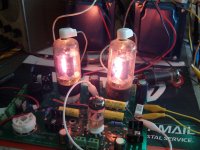
I also saw references in some of the links here to running tubes in the red plate region full time with no ill effects. My extensive testing in this area reveals that the hotter you run any tube, the more "gas" it will create as ions are released from the impurities in the materials used in its construction. Some NOS tubes from the 70's and older can be run quite hard since they were well made. Red plate a new production tube and you will replace it soon. Note that a tube that fails from "gas" will usually go into a red plate runaway condition in its final moments. This can take other parts like the cathode resistor and bypass cap with it when it goes.
Extreme test - Total tube life, about 4 hours:
The old textbooks referred to class A as operation where PLATE current flows for all 360 degrees of an audio cycle. This is REQUIRED for a non distorted output in a Single Ended amplifier.
Class A and class AB was further divided into A1 and AB1 where the tube or tubes are operated such that NO control grid current flows at all during any portion of the audio cycle. True class B requires grid current to work correctly, so all class B is technically B2. Class B was usually reserved for PA amps and modulators due to the crossover distortion produced at low volumes. Some "class B" amps do run a bit of bias on the tubes for a little idle current to reduce this distortion. In reality they are class AB amps if the definition is strictly followed.
Class A2 and AB2 allows for some grid current to flow during some of the audio cycle. This usually occurs only on drive voltage peaks at high volumes.
I coined the term A3 about 20 years ago when I was running 811As on a few hundred volts of B+ and had to run a lot of POSITIVE voltage on the grid to get them to draw enough plate current to be useful. Here grid current flows for all of the audio cycle, so I called it A3. Later on, I tried to tame some of those 35 and 40 watt beam triodes like the 6HV5 designed for TV HV regulators. Again, you need a few volts of positive bias to get some plate current with less than 500 volts of B+ with a Mu of 300 and a Gm of 65000 it doesn't take much drive, so grid current will always flow.
Since the term A3 never appeared in the old vacuum texts it has no strict definition and obviously means two different things here.
I also saw references in some of the links here to running tubes in the red plate region full time with no ill effects. My extensive testing in this area reveals that the hotter you run any tube, the more "gas" it will create as ions are released from the impurities in the materials used in its construction. Some NOS tubes from the 70's and older can be run quite hard since they were well made. Red plate a new production tube and you will replace it soon. Note that a tube that fails from "gas" will usually go into a red plate runaway condition in its final moments. This can take other parts like the cathode resistor and bypass cap with it when it goes.
Extreme test - Total tube life, about 4 hours:
Attachments
6AC5 runs that way, normally driven by a low mu triode.The main advantage is that it avoids the wild swing in grid impedance from a zero grid current condition to that sudden drop when grid current is drawn.
I tried experimental circuits like that a while back using a 6F6 driven by a 6SN7 triodes paralleled as a CF
Attachments
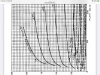
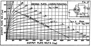
And those positive grid drive curves LOOK like pentode curves. Can’t do that with all triodes - most of the modern stuff won’t that much grid current (See dashed lines). Some of the stuff meant for vertical deflection DOES have positive grid curves because they still did it. Those circuits usually used transformer drive so positive grid drive was easy. But when the 6L6 came out no one had to resort to darlington connected tubes anymore so it fell out of favor for audio amps.
Attachments
But when the 6L6 came out no one had to resort to darlington connected tubes anymore so it fell out of favor for audio amps.
But it is still an interesting design challenge 😎
One is free to build anything they want these days. Just don’t TRY that with new production tubes. Look for the old stuff that was used at the time. Triodes made for vertical deflection use should be able to take the beating.
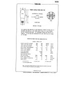
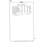
During the late 1930s several composite tubes such as the 6B5, 6N6G. 25B5 & 25N6
containing both the driver CF & an audio power section were put on the market, in particular by Triadyne.
Their 13 page document covering the 6B5 is a good reference for those interested enough to open the PDF.
The socket pin out was compatible with any of the common pentode power tubes of that time.
There was a minor advantage, in most cases they were self biasing. The 6N6G could be pushed a bit at the top end with a simple bias hookup.
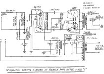
Rockolab built a PP amp using 6B5s, I think these went into Juke boxes.
For the PDF Challenged members on DIY some of the data has been converted to JPGs.
The drawing of the 6B5 internals appear to show a pentode as the output section.
FlaCharlie, often seen here on DIY has built several amps using these toobZ, 👍
containing both the driver CF & an audio power section were put on the market, in particular by Triadyne.
Their 13 page document covering the 6B5 is a good reference for those interested enough to open the PDF.
The socket pin out was compatible with any of the common pentode power tubes of that time.
There was a minor advantage, in most cases they were self biasing. The 6N6G could be pushed a bit at the top end with a simple bias hookup.
Rockolab built a PP amp using 6B5s, I think these went into Juke boxes.
For the PDF Challenged members on DIY some of the data has been converted to JPGs.
The drawing of the 6B5 internals appear to show a pentode as the output section.
FlaCharlie, often seen here on DIY has built several amps using these toobZ, 👍
Attachments
The 6B5 looks similar to what Shishido called "dynamic coupling", a cathode follower straight into the grid of the next tube without reference to ground.
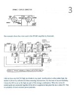
I built guitar amps from stuff salvaged from dead TV sets as a kid. I got a job at Motorola when I was 20 and pretty much abandoned tubes except for occasional guitar amps. Sometime in the1980's I started tinkering with vacuum tube HiFi amps. One of the first SE amps I built used a triode wired 6V6 cathode follower directly feeding the grid of an 811A with no resistor to ground or anything else. I found the schematic on the web and built it as presented even though it didn't look right to me. It worked and didn't sound half bad, but it worked better when I put a resistor from that cathode - grid junction to a negative power supply. This was 20 some years ago so I can't remember the details like parts values and voltages. I can't find the old schematic either.
Shishido was late to the party, The RCA Tube Manual RC-14 called it that in 1940.The 6B5 looks similar to what Shishido called "dynamic coupling",

George - sounds like putting some decent amount of standing bias in your driver resulted in it ”working better”. 6V6’s are kind of “squished” with little current in them. The grid currents in those output tubes may be “high”, but 10 or so mA isn’t “that high”. Even the classic dynamic coupled may have benefitted, but adding another negative bias to things adds cost and complexity.
When I did the same thing with an 808 driven by an 807 CF, I got much better results after adding a choke from the CF to ground. 808 has lower mu than 811 and needs to dip into negative grid voltage for max power.
I also created a local feedback loop by connecting the 807's screengrid to the UL tap on the output transformer. I seem to remember that it worked quite well but the G2 voltage rating of the 807 was violated. That was just a breadboard experiment ten years ago, I guess I could use 6L6GC or similar with an adequate G2 rating if the amp ever gets built.

I also created a local feedback loop by connecting the 807's screengrid to the UL tap on the output transformer. I seem to remember that it worked quite well but the G2 voltage rating of the 807 was violated. That was just a breadboard experiment ten years ago, I guess I could use 6L6GC or similar with an adequate G2 rating if the amp ever gets built.
Check post #24. UL connexion in this operating mode is the plate of the driver taken to the UL tap.I also created a local feedback loop by connecting the 807's screengrid to the UL tap on the output transformer. I
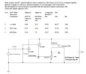
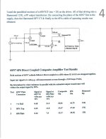
All shows up in the actual measurements I ran on the 6F6 G1 & G2 driven by the 6SN7 CF..
The grid dissipation is not as extreme as we may think, altho the current may seem high for a grid the forward voltage is low.
Watts = Volts x Amps. And a lot of it is on the screen of the tubes I used.🙂
That Rockolab amp running PP 6B5s in my earlier post could easily be run UL if the OPT had UL taps. 👍
Last edited:
All shows up in the actual measurements I ran on the 6F6 G1 & G2 driven by the 6SN7 CF.
Nice, looks like there's quite a bit of Rp reduction by doing so, which would be most welcome.
My idea was to reduce the extra current drawn through the transformer primary by only connecting the screen grid to the UL tap but that leaves the driver tube in an awkward situation where the G2 voltage swings from perhaps 400V at idle down to maybe 250V and up to 550V while the plate-cathode voltage only swings a few tens of volts. Probably not a good thing for an 807, with their kind of fragile sceens.
Last edited:
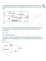
While I was looking at the so-called Class A3 connexion I had found that the plate of the driver triode acted same as the screen in a regular pentode,
I got some numbers from the simple SE hookup to the tapped OPT, the question was how effective a voltage change on the driver plate was.
Thru a 1:1 common audio transformer, 10 volts was connected to the plate of the 6SN7, I measured 1/2 volt on its cathode. See page 5 of the report.
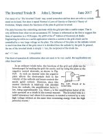
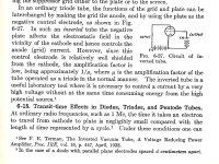
Sure enough in Terman's text book he tells us circa 1930 the inverted triode has a mu' of 1 / mu. For the 6SN7 that would be 1 / 20.
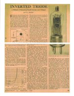
The inverted triode (not the hookup we refer to today) is a useful device. The attached shows one specially built to measure very high voltages.
The six page thing is something summarizing a lot of the work, I gave as a talk to the local vintage radio club.
And no, I don't collect olde radios, I've got too much stuff here already. Took two printers & a gutted desk top to the electronic bone yard yesterday.
Some here on DIY will remember Steve Bench. Steve did a lot of unusual circuits, one of them uses triodes in the inverted mode.
That means driving the plate(s) will a very high voltage & driving the loudspeaker from the grid(s) of the tubes. And it works.
I checked just now, this link works-
http://diyaudioprojects.com/mirror/members.aol.com/sbench102/inverted.html
I got some numbers from the simple SE hookup to the tapped OPT, the question was how effective a voltage change on the driver plate was.
Thru a 1:1 common audio transformer, 10 volts was connected to the plate of the 6SN7, I measured 1/2 volt on its cathode. See page 5 of the report.
Sure enough in Terman's text book he tells us circa 1930 the inverted triode has a mu' of 1 / mu. For the 6SN7 that would be 1 / 20.
The inverted triode (not the hookup we refer to today) is a useful device. The attached shows one specially built to measure very high voltages.
The six page thing is something summarizing a lot of the work, I gave as a talk to the local vintage radio club.
And no, I don't collect olde radios, I've got too much stuff here already. Took two printers & a gutted desk top to the electronic bone yard yesterday.
Some here on DIY will remember Steve Bench. Steve did a lot of unusual circuits, one of them uses triodes in the inverted mode.
That means driving the plate(s) will a very high voltage & driving the loudspeaker from the grid(s) of the tubes. And it works.
I checked just now, this link works-
http://diyaudioprojects.com/mirror/members.aol.com/sbench102/inverted.html
Attachments
-
 The Inverted Triode_0001.jpg409.4 KB · Views: 86
 -
 The Inverted Triode_0002.jpg331.3 KB · Views: 90
 -
 The Inverted Triode_0003.jpg291.7 KB · Views: 97
 -
 The Inverted Triode_0004.jpg239.1 KB · Views: 93
 -
 The Inverted Triode_0006.jpg211.6 KB · Views: 83
 -
 Inverted Triode as a Device in a HV Measuring System.jpg814.9 KB · Views: 79
 -
 Inverted Triode Operation Terman.jpg172.6 KB · Views: 79
 -
 The Inverted Triode_0005.jpg222.1 KB · Views: 86
Makes sense, 6SN7 mu is ~20 so a 10V change on the plate should cause a 0,5V change at the cathode, assuming a constant plate current.the question was how effective a voltage change on the driver plate was.
Thru a 1:1 common audio transformer, 10 volts was connected to the plate of the 6SN7, I measured 1/2 volt
I've thought about using a 12B4A or similar as a cathode follower with its plate connected to the UL tap for NFB but instead of connecting the cathode directly to the power tube's grid, it would drive a Mosfet which drives the grid. That way I wouldn't have to draw a big, non-linear grid current through the OPT.
None of you experts has mentioned A1.5 and A2.5 both sit beTween A1 AND A3.
While this post originated nearly 10 years ago Jack Elliano recently stumbled upon it. He is retired now for the most part and doesn’t post on this forum or others for that matter. However, Jack would like anyone who reads this post to know that he is available to discuss Class A3 topology if you email him at electaudio@cox.net. From his perspective there seems to be some assumptions and misinformation here that can be easily cleared up by contacting him.
From my perspective I can say this. I worked with Jack for several years. I recall back around 2012 or so he wrote a paper on Class A3. We were at THE SHOW when it was still held at the Flamingo in Las Vegas, and we were sharing a room with Fritz Heilor of Fritzspeakers. Jack showed me the paper and after I read it, he and I visited Ralph Karsten of Atmasphere (who Jack and I knew as well). Ralph read the paper and was immediately impressed with Jack’s research and theory on Class A3. From that point forward Jack started designing several Class A3 circuits, the first of which I believe used the 6A3 tube. Recently Ralph Karsten responded to a post on the Audiogon forum where he said, “Tubes have not seen much evolution in the last 40 years by comparison. The big advances in the tube world have come from improved materials for construction (better capacitors and resistors for example) and not to put too much of a point on it, but innovations from designers. I'm one of those designers having several patents in the OTL world; another is David Berning with his excellent zero hysteresis radio frequency coupling system (usually called 'ZOTL' a meaningless acronym created by Harvey Rosenburg; they are not OTLs...) and perhaps Jack Elliano, who to my knowledge is the only one to push SETs further, with his patented class A3 technology and Ultra Path design.”
This is the link to the post: https://forum.audiogon.com/discussi...=Jack+Elliano+Class+A3&postid=2614255#2614255
I found some patents for Ralph Karsten, but was not able to find any for the class A3 from Jack Elliano. Someone has a link?
- Home
- Amplifiers
- Tubes / Valves
- What the hell is Class A3?