tl;dr the old rule of thumb says you want 6db of gain margin and 45 degrees phase margin. You may need more than that to avoid EMI; try 20db of gain margin and 60 degrees of phase margin.
There's an FM radio transmitter in my neighborhood. I've seen two different preamps pick its signal up audibly. Neither device contains an intentional tuner.
In each case the FM interference is quiet -- inaudible with a signal playing, and with no signal playing, the FM station is just above the noise floor in a quiet room. You can tell it's there, if not make out what they're saying.
In each case, spice predicted the preamp had adequate stability margins: better than 45 degrees of phase margin and 6db of gain margin. (I've heard both 6db and 10db as recommended minimums for gain margin.) In both cases, the ULGF was fairly high, in the 10MHz to 20Mhz range.
Playing sharp squarewaves through both preamps showed nothing untoward, no hint of oscillation. Yet the FM pickup was there.
On one of them, I modified the frequency compensation for more generous margins in spice: 24db gain margin, 60 degree phase margin, and a ULGF right around 1MHz.
This fixed the FM pickup. It's completely gone.
Why does it work? The reduced ULGF keeps the critical segments of the loopgain plot well below frequencies where parasitics pop up. Simulation should match the real circuit well in the single-digit MHz range, so its stability prediction is believable. At 100Mhz where the RFI is, loopgain is now far below unity. This loop shouldn't be able to do anything at 100Mhz.
We can get generous margins without sacrificing in-band feedback:
This probably applies to power amps and line/pre amps alike, though I've only really seen bad RFI with preamps.
There's an FM radio transmitter in my neighborhood. I've seen two different preamps pick its signal up audibly. Neither device contains an intentional tuner.
In each case the FM interference is quiet -- inaudible with a signal playing, and with no signal playing, the FM station is just above the noise floor in a quiet room. You can tell it's there, if not make out what they're saying.
In each case, spice predicted the preamp had adequate stability margins: better than 45 degrees of phase margin and 6db of gain margin. (I've heard both 6db and 10db as recommended minimums for gain margin.) In both cases, the ULGF was fairly high, in the 10MHz to 20Mhz range.
Playing sharp squarewaves through both preamps showed nothing untoward, no hint of oscillation. Yet the FM pickup was there.
On one of them, I modified the frequency compensation for more generous margins in spice: 24db gain margin, 60 degree phase margin, and a ULGF right around 1MHz.
This fixed the FM pickup. It's completely gone.
Why does it work? The reduced ULGF keeps the critical segments of the loopgain plot well below frequencies where parasitics pop up. Simulation should match the real circuit well in the single-digit MHz range, so its stability prediction is believable. At 100Mhz where the RFI is, loopgain is now far below unity. This loop shouldn't be able to do anything at 100Mhz.
We can get generous margins without sacrificing in-band feedback:
- Use any of the compensation schemes with two LF poles and a zero at a couple of hundred kHz. I like TPC but TMC can work, lead-lag can work. They all provides >60db of feedback in-band while allowing for low ULGF in the 1-2Mhz range.
- If you use a lead cap across the NFB resistor to improve phase margin, add a resistor around 1k in series with the lead cap to improve gain margin too.
This probably applies to power amps and line/pre amps alike, though I've only really seen bad RFI with preamps.
Last edited:
You may need more than that to avoid EMI
Let me be a bit more complicated.
There are three ways to pick something from outside of the device:
1. From the input
2. From the mains supply
3. From the output
Desired signals are fed to input in a limited freq range and device are better to virtually consume no current, output current must return to a device without any additives, and of cource we need to reject any from the mains except supply current and such a current are better to have no sonic components.
So, please let me define that any pretending "for something more than usual" device must have at least three filters for such interconnections, can i?
So we need at least:
1. 60 dB CMRR from the input side from base amps topology with not less from input filter at freqs where topology are unable to achieve such a value and as small signal current at the input as possible.
2. 60 dB CMRR from mains in any freq range +-octave around device ULGF and no sonic components in consuming current.
3. 60 dB CMRR from the output again around octave near ULGF for excluding any pick where negative feedback becomes helpless.
Without being sure given values achieved talk about frequency compensation influence becomes true hard.
I have to say frequency compensation is a hard way to screen out radio transmissions.
I have 33 pf to 68 pf rca center to analog ground rca ring on a couple of mixers. I have a 11 turn toroid choke on the DC power supply entry of one mixer, close to the input jack. Salvaged from a PCAT switcher supply. If the output picks up RF a 11 to 14 turn coil series that should help. My mixer doesn't pick up RF anymore. But a S100 amplifier did, before I put 11 turns around a 10 ohm wirewound resistor, parallel to the resistor, next to the output screw strip. End of sports talk AM radio in the church organ speaker.
All above products are in steel cases. Preamp lacks a steel case, add one.
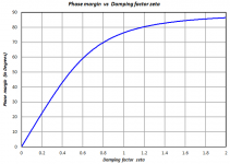
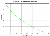
I consult the plots shown below, which assume a second order linear system. Then I choose a phase margin which provides acceptable transient overshoot and acceptable frequency domain gain peaking.
Take a look at the green curve. When phase margin equals 45 degrees, transient overshoot is 25 percent (!)
_
Take a look at the green curve. When phase margin equals 45 degrees, transient overshoot is 25 percent (!)
_
Attachments

Could it be that the two problems are unrelated? Stability is stability and if the circuit is stable, then the problem is RFI ingress. Better to design the compensation to give you the needed feedback and phase margin, and filter RFI where it enters the circuit.
Both preamps had RFI ingress coming through the inputs. It was common-mode: a meter RCA hooked to the input, with a shorting plug at the other end, was enough antenna to get it going. A small cap from signal to signal-ground at the input didn't help.
On one of these circuits, I'd tried and exhausted a bunch of RFI filtering opportunities with no improvement. It's a Sanyo C-55, with a serpentine ground line that follows the signal on a winding path through the preamp. A long linear structure like that could have standing waves at FM frequencies, I thought? So I tried tying it to itself with small resistors, on the order of 10 ohms. There were some points where the serpentine ground was coupled to the chassis with small caps, on the order of nanofarads -- I tried replacing those with 10 ohm resistors on the theory that a resistive load should absorb RF energy better than a reactive load. I added 470 ohm resistors between the preamp output node and the output jacks, to isolate the amp from loading effects, whether capacitive or antenna-like. None of these edits made a bit of difference.
I have a 300MHz scope. This scope also picks up the FM carrier wave, even with the probe just clipped to itself, it draws a 30mV 100Mhz wave. And that's superimposed on whatever you probe. And of course the probe itself adds an antenna to whatever you probe.So the scope isn't much use for seeing RF effects directly.
I hear you. I have FM transmitters within a couple miles of here and I pretty much have to use the BW switch on my scope all the time because there's just no keeping these signals out of my circuits.
- Home
- Source & Line
- Analog Line Level
- What stability margins do you design for?