Hy SY,
Not yet, I've been thinking of it, but mine is still working. What did you do? I don't like it cycling.
I won't modify it until I can get hold of another to use as a control. The one I got was half way through being "audiophilized". It was such a mess I just stripped it and rebuilt it by the manual with original part values. I took it down to the bare chassis. I was amazed at how good it sounded when I sparked it up. My wife loves it too (actually, everyone does). The point is that this is how it was designed and it's great.
I guess I'm afraid to mess with something that works well.
-Chris
Good point- it's a solid circuit. Originally, I just converted it to fixed bias. Later, I changed the output tubes to EL37, a good move. Input tube got changed to a 5691, then eventually a regulator found its way onto the chassis.
At this point, I've stripped the chassis back down again in preparation for a new input stage and power supply.
The little soft-start job got replaced with a 555 circuit and a relay.
At this point, I've stripped the chassis back down again in preparation for a new input stage and power supply.
The little soft-start job got replaced with a 555 circuit and a relay.
Now, if I could buy the output transformers new and power transformer new I'd be up for some serious playing around.
I guess I should stop hyjackin this poor thread.
-Chris
I guess I should stop hyjackin this poor thread.
-Chris
PRR,
That's some serious reading for me, proved some of my questions and I'm very thankful for that.
Jojo
That's some serious reading for me, proved some of my questions and I'm very thankful for that.
Jojo
anatech said:Now, if I could buy the output transformers new and power transformer new I'd be up for some serious playing around.
I guess I should stop hyjackin this poor thread.
-Chris
Nah... don't worry about hijacking this thread... I just hope to learn from the discussions.
🙂
Thanks Jojo,
Aside from replacing the thermal switch I was thinking about using a SS regulator (already designed) to run the front end (incl. the phase splitter). I find it really drops the noise floor and gets rid of a lot of "clutter" when you start driving an amp.
Possibly some old Heath output transformers may be worth playing with. What do you think of those SY? 6L6GC or 6BQ5 types.
I also have an old Sansui AU-111 to restore. The 6L6's are cooped up in a little space. Right now I have numerous cap problems and I need info on bias setup, etc ..
-Chris
I don't have a lot of experience with the Heathkit OPTs, alas. But if you find one with decent iron...
Now thats the $64K question. It's also why I was attracted to the Eico in the first place.
Strangely, I don't like the McIntosh MC-40's I had. I even went over them, which helped. They sounded very sterile. Bye Bye McIntosh's.
-Chris
Strangely, I don't like the McIntosh MC-40's I had. I even went over them, which helped. They sounded very sterile. Bye Bye McIntosh's.
-Chris
hey guys,
I encountered a DIY'd amp (an old EL34 PP cathode bias 😀 ) that looks like the beams of the tubes are alternating, when one is bright, the other is dim and the amp makes this hum sound in the speaker much like when a lightsaber is being swing around.
I isolated the problem being caused by the separate preamp, had the psu reworked and it worked ok, though sometimes it still does that hum-hum thingy.
What was happening in the amp? What may have caused the tube beams to alternate like that?
TIA
> like when a lightsaber is being swing around.
Are you living in another universe? Or do you mean some plastic-stick sound? (I never hung with StarWars crowds.)
> when one is bright, the other is dim and the amp makes this hum sound in the speaker ...I isolated the problem being caused by the separate preamp, had the psu reworked and it worked ok, though sometimes it still does that hum-hum thingy.
Without my lightsaber, all I can guess is motorboating. Sub-sonic feedback, generally through the power supply, aided by mismatched resistors.
This is Positive Feedback. It will kill tubes, power-caps, other parts, because the tube is driven into heavy conduction, then relaxes, then the other tube conducts heavy.
Power supply cap replacement is nearly a "given" on Classic Era tube amps. Don't do a half-way job: they were all there for a reason and they were barely big enough when new. When old and weak, bad things happen.
Check the phase-splitter and be sure the "equal" resistors are really EQUAL (within 10%; 5% is better). In my ArKay, the root cause was two "47K" resistors that drifted: one to 51K, the other to 90K. Hot carbon-comp resistors can drift a long way from their marked values and still "work". In this case, the power filtering assumed the phase-splitter would be nearly-balanced and reject low-frequency wiggles coming back from the output stage thumps; with 51K and 90K, it didn't. (The amp was only 15 years old at the time so the power caps were not yet weak from old-age.)
PRR,
😀 Was pertaining to the sound fx that is what I hear. The amp works fine with a different preamp, it only does that thing with my friend's preamp which he also built.
Anyway, will still check the whole psu for the preamp and amp just to be sure.
Thanks!
😀 Was pertaining to the sound fx that is what I hear. The amp works fine with a different preamp, it only does that thing with my friend's preamp which he also built.
Anyway, will still check the whole psu for the preamp and amp just to be sure.
Thanks!
What are the signs of an overheating output tube?
Would I know this just by looking, or I will hear something from the speakers?
TIA
Would I know this just by looking, or I will hear something from the speakers?
TIA
Hi Jojo,
Look at the plates of the output tubes in a darkened room. When they are starting to overheat you will see dull red ovals on the plates. In a bad case, you can see this in normal ambient light. The only light source you should see are the heaters glowing in the center of the tubes.
-Chris
Look at the plates of the output tubes in a darkened room. When they are starting to overheat you will see dull red ovals on the plates. In a bad case, you can see this in normal ambient light. The only light source you should see are the heaters glowing in the center of the tubes.
-Chris
hi Chris,
was reading stuff over the internet and they say that the plates will "glow" when 1. too much voltage and 2. dying tubes. looks like an overheating tube can be distinguished right away.
thanks!
was reading stuff over the internet and they say that the plates will "glow" when 1. too much voltage and 2. dying tubes. looks like an overheating tube can be distinguished right away.
thanks!
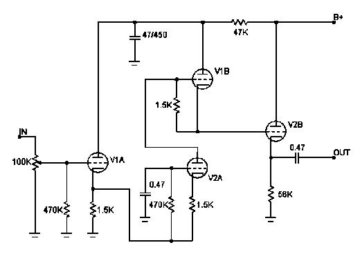
was looking over some circuits I have and was intrigued by this. v1a and v2b are cathode followers, what bothers me is i can't recognize what topology is v1b and v2a?
regards
regards
> topology is v1b and v2a?
Cathode-driven SRPP.
In this case: the "PP" part of the SRPP is ineffective, the load is an open grid. The gain is very much less than Mu/2 because of all the added resistance between the input and V2A cathode. (Roughly 0.3*Mu.) Input overload is probably low compared to supply voltage times gain. And you would think that the 1.5K under V1A would be lower, since it handles two cathode flows. Yet I'm pretty sure it will "work" as is. I'm not sure what audio advantage it has over a simple volt amp and cathode follower.
Of the making of many tangled circuits, there is no end.
so it is an SRPP, or something like it. i was a bit confusing because I haven't seen SRPP circuits in such an arrangment in the past.
- Status
- Not open for further replies.
- Home
- Amplifiers
- Tubes / Valves
- What more do I need to know?