lineup said:
this question has got not one answer, but many
depending on what your goal is
and what is the situation at hand
Onvinyl:
I think Conrad is right in claiming to look at the whole ciruit, reg + amp together.
I think this is not much different to what I just said.
")
Like i mentioned in previous thread...
Depends on what and how much the power supply does to the audio circuit... Does the audio circuit meet requirements..
For example: As the power supply regulation gets worse, the audio intermods typically get worse as well... Does this matter??? Well if this level of intermods are buried in the poor noise floor then no...Or possibly the listener does not detect such small detail.. Also as mentioned by other post, depends on the PSRR of the over-all topology......again we arrive at the same question, does the entire audio circuit meet your requirements.....?
Chris
I want to treat the ps as a "black box". Looking into its output terminals, I want it to have low impedance from DC to a moderate frequency, but not too low. I do *not* want my ps bypassed with film caps! Of necessity, the thing will be located at least some inches away from its load, so there'll be lead inductance. Zero output impedance, even if achievable, isn't desirable. Depending on the application, I want a few ohms, and I'd rather use very low esr caps and a bit of resistance wire, rather than depend on an esr that's unknown and may change over time. Most circuits don't have great high frequency power supply rejection, so I try to keep the noise a few times lower than common sense probably suggests. To avoid a mid or high frequency noise peak with 3-term regulators, that bit of resistance wire again comes into play. If I ac couple the scope and look at the ps in operation, I don't want to see music on it, but a high output impedance will result in exactly that, so IMO choosing the output impedance for sufficient stiffness but good stability is the trick. My supplies aren't very interesting- they just sit there at a boring constant voltage. I put more effort into HF bypassing right at the circuit- that's where I want the HF energy storage because that HF energy isn't coming through the inductance of the supply wires anytime soon.  I also don't want HF signals on the ps wiring where they can radiate or couple, something the local bypassing also does for you. I don't want RF anywhere, so bypassing the ps bridge diodes is required. Finally, I consider safety ground and transformer fields part of ps design, but that's for another thread.
I also don't want HF signals on the ps wiring where they can radiate or couple, something the local bypassing also does for you. I don't want RF anywhere, so bypassing the ps bridge diodes is required. Finally, I consider safety ground and transformer fields part of ps design, but that's for another thread.good conrad
i would gladly use one of your power supplies
no mysterious thing
only good audio engineering
my self
1. my amplifiers are always built for maximal PSRR for the topology used
i use mostly discrete but on occations some op-amps, too
2. means often ccs sources and/or current mirrors
3. whenever i use a design with lower PSRR & i can think ps can influence performance to a degree
i take extra care to get a maximally clean supply
4. you see here that my first priority deals with the application at hand
5. secondly i have to take measures & adjust my supply with some extras, should i judge this necessary
6. there are no general model i use for all my power supplies
7. i make it custom to current situation/application = they should fit together & perform optimal or close to optimal
Lineup
Eva said:A constant voltage source can't alter an audio signal. Regulation has to be made extremely loose in order to measure significant signal changes.
On the other hand, the placebo effect has been very well documented and consistently proved over the years, unlike every word written about the subjective "sonics" of electronics.
Eva, on this occasion you completely missed the point of the original post. Your answer (quoted above) assumes 'a constant voltage source', i.e. a perfect regulator. However the original question (when interpreted) from Onvinyl assumes a non-perfect voltage source and asks which non-perfect parameters will affect the performance of the target circuit.
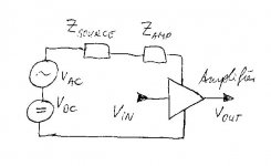
Hi, a way of looking at this that I find useful is the following (please have a look at the attached picture):
1) the PS will provide DC but also some AC. It reaches the amplifier through the two impedances Zsource and Zamp
2) The varying energy need of the amplifier will reach the power supply through the same impedances
3) unfortunately, ripple, PSRR and all the rest can only be looked at at the midpoint between the two impedances...
that implies IMHO the following: when designing a power supply (as making Zsource zero is impossible), at least you should try to make it identical across the audio frequency range - that should avoid the "big ticket" mistakes and sonic flaws.
once that is done, the design (== interaction of power supply and amplifier) moves into the "personal taste" space, with foil caps, shunt regs, snake oil, and similar topics.
the next level of complexity then would add parasitic inductances especially for high-current paths (e.g. class-B output stage - yes class-A draws current too but its DC most of the time.), back EMF of the loudspeakers, increased source impedance through line filters, the effects of different capacitor types at the impedance midpoint, etc etc etc..... I think this is what OnVinyl wanted to talk about.
just my two cents....
Attachments
hesener said:
3) unfortunately, ripple, PSRR and all the rest can only be looked at at the midpoint between the two impedances...
I can't see why this is unlucky unless I got you wrong. If Zamp is the amps's impedance 'seen by' the regulator, then you can look the ripple at the psu-connections of the amp.
What I'm after is a discussion of technical differences of various regulators and their possible impact on sound. If there are no differences in perception of sound quality for me, then I would happily stay with a bunch of 7815 or the like regs.
I would guess that a flat impedance does indeed a lot for good sound.
As I wrote, a superreg as better line regulation and would thus be a better choice for a phonopre, say.
Noro claims in his patent, that a shunt reg provides a cleaner ground, for instance, because it separates the current loops: the current loop between recitfier, caps and reg is closed due to the regs stable, loadindependet currentconsumption, and hence the loop between load and reg is completely separated.
This is the kind of thing I'd like to diskusss.
Or: why does the shunt reg allows 'better' (to me) reproduction of trebles?
Rüdiger
- low noise
- low output impedance
- flat output impedance
- stability with rapid load changes (that one might be easier with open loop circuits)
- clear definition of ground (low impedance ground point)
I really like those features but don't know which regulator out there gives me all of those.
Since I am using active crossovers, I am wondering if I could use 2 regulators - one for the midrange and treble, and the other for the bass. In that case, the first regulator needs to have low noise, low output impdedance at higher frequencies, etc, while the second regulator needs low impedance at low frequencies. Would it make my life easier to find the right regulators?
Onvinyl,
yes thats what I meant. "unfortunately" only since any signal you can see at the PSU connections of the amp will see influence by both the noise coming from the PSU as well as the noise fed backwards by the amplifier, and both are attenuated by both impedances - a rather complex correlation.
simplifying somewhat, if Zsource can be small (which is not so complicated) the noise will be strongly attenuated. typical ways of doing that are big caps parallel with smaller foil caps, and a good regulator.
I have seen a good design using a voltage reference that feeds several source followers with small MOSFETs (or opamps as voltage followers) - fast local feedback loops with low noise. For a preamp with several stages a very good solution, I think. That would even work with tube preamps, since the current is small and the voltage across the MOSFET would be zero at startup, increasing as the tube starts drawing current. (HifiNutNut that might be a solution for you?)
The main advantage of shunt regulators (other than the current loop separation for input noise) is that should noise (voltage spikes) appear at the VCC line, a shunt regulator can absorb it. A "classical" regulator cannot do that as easily - it would have to increase output impedance so it dampens the problems less, whereas a shunt regulator can lower the impedance. (as I write this I am no longer sure that this holds true for both halves of a noise wave, though.... anyone care to comment?)
- Status
- This old topic is closed. If you want to reopen this topic, contact a moderator using the "Report Post" button.
- Home
- Amplifiers
- Power Supplies
- What makes a voltage source sound good?