lumanauw said:Bipolar transistor are made by 3 parts (like layer cake) N,P,N or P,N,P. .... Is the cake drawing I learn at school is not perfect?
Not quite. BJTs are more like concentric rings. The inner ring/core is the emitter, the middle ring is the base and the outer ring is the collector. They are typically drawn like layers which gives the perception that you could reverse the leads and it would be symmetric. In reality since it is not symmetric, reversing the C/E leads results in a very poor performing transistor (although not necessarily fried).
http://people.deas.harvard.edu/~jones/es154/lectures/lecture_3/darmstadt/sld021.htm
However, MOSFETS tend to be made symmetrical, as is drawn in school. It is only the manufactured Base/Source strapping that causes the pins to be defined. A 4-terminal MOSFET would be usable in either direction.
Pure silicon isn't glass and it isn't an isolator, but a semiconductor
Sorry, I'm not very careful with that writing. Pure Si surely be different than SiO2. This spontaneus error comes from the impact of teacher's story in school. When he first explains about Silicon semiconductor, he explain that this Si comes from ordinary sand, like in the school yards (which is glass made of)
Really waiting for your long explenation version. I'm hoping the final result of your explenation can guide me to pick current operation point and voltage operation point, in normal usage or cascode, for every mosfet and bipolars (for various functions in audio amplifier offcourse).
I'm very interested in low voltage cascoding with high current, because I think it can lead us to class A with low or more controlled dissipation.
pjacobi said:So, yes, operating a BJT as with Vce smaller than Vbe is perfectly sensibly for some few applications, but in contrast, operating MOSFETs with Vds smaller than Vgs is fairly normal.
Actual testing confirms that you start getting real deterioration
below 2 volts Vds on a cascoded Mosfet , but in truth they still
sound better with more voltage than that. 2 volts is simply the
minimum.
Hi, Mr. Pass,
While searching this forum about that patent, I found this
I it true you have not built anything commercial based on that patent because it is not as good as true class A?
Your answer will makes me think harder about how transistor works.
Also, check out my patent #5,343,166. This is a unique use of cascoding which I have yet to incorporate in a product.
While searching this forum about that patent, I found this
I believe he said he has not used that in 17? years or something because he did not like the sound compared to a true class A
I it true you have not built anything commercial based on that patent because it is not as good as true class A?
Your answer will makes me think harder about how transistor works.
Hi Nelson, All,
Thanks for your guidance here.
I am assuming my posts are simply part off topic here, as I was thinking about MOSFETs on linear duty in different rôles, whereas the original poster was asking about the output power devices?
What I was trying to say, is that in absolute numbers, all stages and rôles included, a very high percentage of MOSFETs operate at tiny Vds. I was espescially thinking of all the cascoded current sources and mirrors in VLSI.
Regards,
Peter Jacobi
Nelson Pass said:[...] 2 volts is simply the minimum.
Thanks for your guidance here.
I am assuming my posts are simply part off topic here, as I was thinking about MOSFETs on linear duty in different rôles, whereas the original poster was asking about the output power devices?
What I was trying to say, is that in absolute numbers, all stages and rôles included, a very high percentage of MOSFETs operate at tiny Vds. I was espescially thinking of all the cascoded current sources and mirrors in VLSI.
Regards,
Peter Jacobi
Hi lumanauw, All,
I just realized, that you are especially thinking about the output (power) stage. For this stage, cascoding BJTs doesn't look that good, as power BJTs 'suffer' from an effect named 'quasi saturation', which makes operating them at low Vce less desirable and less linear.
Googling for '"quasi saturation" BJT' will give you some links, but unfortunately I've found no clarifying graphic, except this one, which is less than optimally clear:
http://www.weberconnect.de/PA_Modeling_AACD1998_Kopenhagen.pdf (page 4).
High current, low voltage devices, like Sany 2SA1292/2SC3256, are better in this respect and may be considered for experiments.
You can used a mixed casode stage, with a MOSFET operating at constant Vds and a BJT for voltage amplification, but I'd guess that apart from its unusualness, there wouldn't be many advantages.
lumanauw said:[...] I'm hoping the final result of your explenation can guide me to pick current operation point and voltage operation point, in normal usage or cascode, for every mosfet and bipolars (for various functions in audio amplifier offcourse).
I'm very interested in low voltage cascoding with high current, because I think it can lead us to class A with low or more controlled dissipation.
I just realized, that you are especially thinking about the output (power) stage. For this stage, cascoding BJTs doesn't look that good, as power BJTs 'suffer' from an effect named 'quasi saturation', which makes operating them at low Vce less desirable and less linear.
Googling for '"quasi saturation" BJT' will give you some links, but unfortunately I've found no clarifying graphic, except this one, which is less than optimally clear:
http://www.weberconnect.de/PA_Modeling_AACD1998_Kopenhagen.pdf (page 4).
High current, low voltage devices, like Sany 2SA1292/2SC3256, are better in this respect and may be considered for experiments.
You can used a mixed casode stage, with a MOSFET operating at constant Vds and a BJT for voltage amplification, but I'd guess that apart from its unusualness, there wouldn't be many advantages.
Hi, Pjacobi,
Thanks for the links you pointed. They helps me understand more about transistors.
About the original question, it is not about final stage only. But I mean is for all stages of audio power amplifier. The point is to understand about how a single transistor works, and then I can decide to design or choose the good operating point for every stage in audio power amp.
What is really the way to pick good operating point for a certain transistor? What graph should be looked at, in the datasheet there are many graph.
Thank you
lumanauw said:What is really the way to pick good operating point for a certain transistor? What graph should be looked at, in the datasheet there are many graph.
As this is neither Pass Labs nor MOSFET anymore, I've put my answer at:
http://www.diyaudio.com/forums/showthread.php?s=&threadid=28262
Regards,
Peter Jacobi
lumanauw said:Is it true you have not built anything commercial based on that patent because it is not as good as true class A?
You must be referring to my dynamic bias patent. I haven't
marketed a product using it since about 1978, which makes it
about 26 years. Nothing wrong with the concept, and variants
of dynamic bias have been put to use by Hawksford and Cordell
(and now Halcro) since then.
In the Threshold products such as the 800A, the bias was set
at about 1/2 the figure you would see in a "pure" Class A amp,
so it idled at about 200 watts per channel, which was also its
power rating.
Unfortunately the idea was put to use by a lot of outfits that
chose to bias the circuit at very low levels, which in my opinion
did not sound nearly as good, but could still be technically
referred to as Class A because the output transistors did not
go into shutoff over the operating cycle. I don't think it sounds
as good as something with a really high bias, dynamic or not.
In any case, I withdrew the dynamic bias amplifiers from
production as the reputation of the approach was suffering
due to the compromised copies on the market.
In any case, I withdrew the dynamic bias amplifiers from production as the reputation of the approach was suffering
due to the compromised copies on the market.
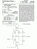
While searching in this forum for this patent, I also found this.
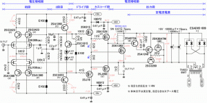
Is this still be in the patent? For me the K1380 is working only like buffer with high bias, or is it indeed the dynamic bias patent.
Attachments
It appears that the bias voltage would be fairly constant
on this, so I don't think it would be dynamic bias.
on this, so I don't think it would be dynamic bias.
Yes, now that you point it out, I believe you're right, that's
pretty much the same topology. Nice to see that the
competition takes 10 years longer to figure it out. 😎
By the way, this appears to be a quite sophisticated DIY effort.
😎 😎
pretty much the same topology. Nice to see that the
competition takes 10 years longer to figure it out. 😎
By the way, this appears to be a quite sophisticated DIY effort.
😎 😎
I forgot to mention that if you look at the additional diagrams
inside the patent, you'll see examples of the single-ended
case. Does that give anyone ideas?
inside the patent, you'll see examples of the single-ended
case. Does that give anyone ideas?
I forgot to mention that if you look at the additional diagrams inside the patent, you'll see examples of the single-ended
case. Does that give anyone ideas?
The only page I have on this patent is the one I upload. Does anyone has the picture that Mr.Pass mentioned?
lumanauw
Do you still need a soft copy (scanned) of the complete patent in question? If so please send your email address.
Bey
Do you still need a soft copy (scanned) of the complete patent in question? If so please send your email address.
Bey
- Status
- Not open for further replies.
- Home
- Amplifiers
- Pass Labs
- What makes a mosfet linear?

