The chip is less than 78% efficient. supposedly i would say about half way between 50% and 70% or so.
so.. if You would drive something with 10 watt from this IC, it would present a load of roughly 1.6 watt.
an amplifier is not a static load like a pure resistor of a fixed value.
in fact, it is a verry interesting load, it does mather what You play ( a fixed tone, or music) depends on the load driven by the amplifier (speakers are not a fixed pure resistive load, they are complex impedance, even a 6 ohm nominal impedance speaker can have in its range anything from even down to 4 ohms up to 30 or more ohms. freqvency dependant)
so, in practice usually it is best to take a look at the IC datasheet, multiply the maximum repetative current it can deliver, and multiply by 1.5
a powersupply that can deliver this amount of current at the rated voltage You want the amp to be driven with will most possibly be enough.
Its a very interesting question - as Arty says the load presented depends very much on what music (or test tones) you play. Also the load is non-linear because the chip is a classAB amplifier - its generating current pulses which have harmonic content far beyond the audio range.
Without music playing the loading is close to being a constant current source in that the quiescent current doesn't depend much on the supply voltage. If you don't have output offset correction then there'll be additional current flowing through the speaker's voice coil.
Without music playing the loading is close to being a constant current source in that the quiescent current doesn't depend much on the supply voltage. If you don't have output offset correction then there'll be additional current flowing through the speaker's voice coil.
With the 6 ohm speaker, LM1875 is 53% efficient, which is the portion that goes to the speaker, with the remainder of 47% to warm the heatsink. The sum (53%+47%) is 100% of the power input. I didn't count power used for warming the cables, bridge rectifier, transformer, caps, resistors, etc. . . but hey I'm just estimating here.
TI assigns a 34W total power budget to LM1875, and that is 34W budget shared/split between speaker and heatsink. In their example, 8 ohm speaker, 60% efficiency is then 20W to the speaker AND 14W to warm the heatsink.
The sum is 34. The 8 ohm speaker gets 20W
I think it could do slightly more, so I'll be using 36W total. But, the amp is not 100% efficient, so we'll have to multiply the efficiency by the total power budget. With the amp efficiency at 53% while driving your 6 ohm speaker, just multiply 36*0.53 to see that there will be 19W available to the speaker and 17W to warm the heatsink.
The sum is 36. That 6 ohm speaker gets 19W
That will take approximately 21+21vdc rails, at most.
VA for transformer is not exactly the same as watts (even though both are volts*amps=watts), but the difference is a minor 10% or so (power factor?).
If 6 ohm speaker, it is possible to use up to 36va~40va 15+15vac transformer for each monobloc without excessive risk of exploding the amplifier.
Those are maximized figures.
Exceeding that, could be sketchy and result in reduced longevity.
Pushing LM1875 to max requires current limited supplies most sensibly done with monoblocs.
P.S.
If you wanted a much more convenient stereo build, go get the 12.5+12.5vac 2A center tap transformer at the nearby radio shack. After power board (as easy as one bridge rectifier and a pair of big caps), that's 17+17vdc rails. The results from that option are 13W to most speakers and the excellent convenience that the datasheet sample schematic is optimal at that voltage.
Thanks for you responses.
I am interested in learning, so a "convenient stereo build" is not what I want")
I was planning to do single supply of 44V but from your explanation it looks like 42V may be better. I will drop the 58V from the psu to 42V using LM317 regulator. To handle more current I have to use some power transistor.
I am interested in learning, so a "convenient stereo build" is not what I want
I was planning to do single supply of 44V but from your explanation it looks like 42V may be better. I will drop the 58V from the psu to 42V using LM317 regulator. To handle more current I have to use some power transistor.
ah, this last post helps a lot in understanding what are You interested in :d
http://www.ti.com/lit/ds/symlink/lm1875.pdf
page 3.
see the table, and entry : Current limit
it says a tipical 4A.
therefore, we choose a higher than 4 A regulator.
that would be something that can handle 5A current, or more.
http://www.ti.com/lit/ds/symlink/lm1875.pdf
page 3.
see the table, and entry : Current limit
it says a tipical 4A.
therefore, we choose a higher than 4 A regulator.
that would be something that can handle 5A current, or more.
Might as well do a high end regulator. It only takes one more reg to do it (nested regs). Look up "Tracking Pre Regulator" which can be found in some ST reg datasheets. They'll probably use two of the same. However, a high-spec regulator can be used to provide some finer guidance to a more sturdy regulator that actually drives the load.I am interested in learning, so a "convenient stereo build" is not what I want
A better regulator gets rid of more power noise without either getting rid of some audio signal or interposing its own signal on the audio.
LM1875's protection scheme is incomplete and mostly ineffective. I would have the different preference that the amp should survive the experimenting and therefore it would be good to have something in the chain weaker than the amp. So, a smaller regulator that happens to have a *working protection scheme* may be a little more satisfying. The typical "everything stronger than the amp" approach doesn't work long-term for LM1875 applications.. . .we choose a higher than 4 A regulator. . .
Ok, 4A per LM1875, so for 2 we are looking at 8A. That looks like a lot of amps. There is a fuse on my old receiver psu for 5A near the AC input and it was handling 280W of power. I am only looking at about 10W/LM1875 why are we in need of so much amps, am I missing something?
Also when looking at the spec sheet graphs (THD vs Power Output , THD vs Frequency, Open Loop Gain and Phase vs Frequency graphs) the reference suppl voltage they show is +/- 25V. I am guessing from this that 50V single supply has been tested, so why all this worry about keeping the supply voltage down.
I think there is a confusion regarding single and dual power supply - since most of the posts on the forum is for dual supply, 25V is fine but the equivalent single supply voltage is 50V ! Again am I missing something?
I think there is a confusion regarding single and dual power supply - since most of the posts on the forum is for dual supply, 25V is fine but the equivalent single supply voltage is 50V ! Again am I missing something?
Also when looking at the spec sheet graphs (THD vs Power Output , THD vs Frequency, Open Loop Gain and Phase vs Frequency graphs) the reference suppl voltage they show is +/- 25V. I am guessing from this that 50V single supply has been tested, so why all this worry about keeping the supply voltage down.
I think there is a confusion regarding single and dual power supply - since most of the posts on the forum is for dual supply, 25V is fine but the equivalent single supply voltage is 50V ! Again am I missing something?
The Power Dissipation vs Power Output graphs may contain the answer you are looking for.
Last edited:
You can go for 50 volt single supply.
and You can buil a regulator for 1 lm1875, andf build a notherone for the other.
fuses are quite tolerant stuff.
they do not blow instantly. some fo them are intended to be slow-blow fuses.
depending on the duration, a fuse will not blow even if the current is a magnitue higher than what it was rated for.
a regulator is not like a fuse.
the amplifier will draw current based on the signal (and the load, and the gain settings..etc..) but it will be (with music) something similar to a sine wave. it will have peaks. the regulator must be rated to handle the peaks. the fuse does nt have to be able.
that is why Your reciver managed to get away with a 5A fuse.
other than that, that 280W power may have been P.M.P.O, or musical power, or god knows what kind of messed up numberpumping figure.
(btw, in one way of calculation the lm1875 will give You 240watts of power. some manufacturers of idiotic number came up with the abs. maximum supply voltage multiplied by the maximum peak output current "figure" to represent consumers to high enough watts to make the equpiment HIGHEND. )
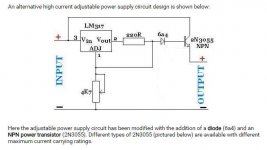
Don't you think one of the following circuit can handle both LM1875s. The transistor is MJE3055T (10A max collector current) and diode 1N5407 (3A max). Thus theoretically I should be able to supply about 10 A at 40 V ? The resistors will be 300 and 10K.
Attachments
Last edited:
yes this can work allso.
You will need a decent heatsink for the transistor, keep in mind.
but it should work. at least no reason i see why it would not.
you might want to include a pot to set the voltage, resistors tend to be not so accurate, and chips differ a bit too. the regulators reference voltage has some spread too. needs to account for that. a proper voltage set is never a bad thing.
allso datasheets show some low value caps needed by the regulator to make sure it works properly. i would consider adding them to this schematic. stability in this application is a musthave.
yes this can work allso.
You will need a decent heatsink for the transistor, keep in mind.
but it should work. at least no reason i see why it would not.
you might want to include a pot to set the voltage, resistors tend to be not so accurate, and chips differ a bit too. the regulators reference voltage has some spread too. needs to account for that. a proper voltage set is never a bad thing.
allso datasheets show some low value caps needed by the regulator to make sure it works properly. i would consider adding them to this schematic. stability in this application is a musthave.
Yes, I have to use a pot, the last time I used fixed resistors the output was off by about a volt but LM3886 did not mind it so much.
For caps I will use a .1u for input and on the output I am planning on LP filter via 4700uH inductor with 4700uF cap to clean the dc. I don't if I need it, when using walwarts it kinda helped but with the transformer-bridge-6700uf cap will it help? may be not?
I think the diode bridge , and the 6700 uF cap before the regulator, and 4700 uF cap after the regulator is sufficient. the inductor can make the circuit ring, i would not use it.
the 0.1 caps are a musthave
the 1875 has verry good powersupply noise supression.
it will do fine like this.
there are several approaches to building it, and this is one available solution.
the 0.1 caps are a musthave
the 1875 has verry good powersupply noise supression.
it will do fine like this.
there are several approaches to building it, and this is one available solution.
I think the diode bridge , and the 6700 uF cap before the regulator, and 4700 uF cap after the regulator is sufficient. the inductor can make the circuit ring, i would not use it.
the 0.1 caps are a musthave
the 1875 has verry good powersupply noise supression.
it will do fine like this.
there are several approaches to building it, and this is one available solution.
Thanks.
yes, you are missing a lot.Ok, 4A per LM1875, so for 2 we are looking at 8A. That looks like a lot of amps. There is a fuse on my old receiver psu for 5A near the AC input and it was handling 280W of power. I am only looking at about 10W/LM1875 why are we in need of so much amps, am I missing something?
The loading on the transformer is not constant.
The loading on the PSU is not constant.
In both cases the loading is complex (i.e. has a combination of reactive and resistive components to the current demand).
A Power Amplifier with zero signal, is effectively a resistance load.
A Power Amplifier with a signal is a constantly changing current demand ranging from peak currents of many Apk to a few mA resistive.
The PSU and local decoupling has to supply all these varying demands.
A regulator is not a good way to meet those varying and complex current demands.
I have a stereo system with 100W trafo giving 2x19V regulated to 22V with 2 lm338 that can deliver max 7A (they also mention 12A). Didn't have any problem yet and don't think I will. Although I use it with a 8 ohm bookshelf speaker.
You should not put big caps after regulators, max they advise is 1000uF. I have 100uF. And 9900uF before the reg.
http://www.diyaudio.com/forums/chip-amps/79303-chip-amp-photo-gallery-239.html#post3416070
By the way regulators will not like 58V supply voltage. Lm317 or 338 doens't like more than 40V.
Last edited:
I have a stereo system with 100W trafo giving 2x19V regulated to 22V with 2 lm338 that can deliver max 7A (they also mention 12A). Didn't have any problem yet and don't think I will. Although I use it with a 8 ohm bookshelf speaker.
You should not put big caps after regulators, max they advise is 1000uF. I have 100uF. And 9900uF before the reg.
http://www.diyaudio.com/forums/chip-amps/79303-chip-amp-photo-gallery-239.html#post3416070
By the way regulators will not like 58V supply voltage. Lm317 or 338 doens't like more than 40V.
The spec says you can regulate very large voltages (100s of volts I guess) as long as the input - output differential is over the specified max, I think it is 40V for LM317.
- Status
- This old topic is closed. If you want to reopen this topic, contact a moderator using the "Report Post" button.
- Home
- Amplifiers
- Chip Amps
- What load does the supply see for LM1875?