I purchased a kit and this is the pre fabricated crossover that it came with. There was no diagram so I traced this from the crossover board but could not make out all the values as they were glued on with some numbers facing down..
It doesn't look like the normal series crossover that I have seen in literature.
Does it look correct or is it wired wrong? I don't want to blow the speakers by playing them with a wrong crossover.
Thanks
Ralph
It doesn't look like the normal series crossover that I have seen in literature.
Does it look correct or is it wired wrong? I don't want to blow the speakers by playing them with a wrong crossover.
Thanks
Ralph
Attachments
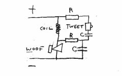
Appears to be wired ok to me. It is a type of xover that effectively includes the drivers themselves as a part of the xover network for the other driver. There are some claims of sonic advantages for this approach, but I've never tried it, partly since nonlinearities of either driver that reflect back to its electrical circuit seem to be to be more likely to affect the other driver.
Its just a variant. The designer wanted that central resistor where it is for some reason, (maybe to prevent circuit resonance?)
Without that central resistor, the circuit would be a standard series x-o because it wouldn't matter which way around you put the woofer and its bypass capacitor.
Without that central resistor, the circuit would be a standard series x-o because it wouldn't matter which way around you put the woofer and its bypass capacitor.
A bit depends on the value of that R that is in the middle.
What is it?
Anyhow it is more of a parallel network than a series network.
Remove the R in the middle and that becomes clear.
It might be a cheap way to boost the HF response of the woofer a bit - the L of the xover is bypassed by the tweeter and then fed into the woofer via the R...
Of course this also may rolloff the woofer more because of the shunting C that is present in series with the R...
If I were making the xover, I'd separate the two legs, and use separate R and C values for each driver.
Of course there might be some wonderful equalizing effect wherein the woofer and tweeter magically match each other as a result of the interactions in that R value.
I'd experiment on the kit.
Run the drivers alone with a handy mic and your soundcard + freeware FFT speaker measuring software. You don't need anything calibrated for this. Ur looking at the match between the woofer and the tweeter only. Or mostly.
See what they do alone, no xover, then with this xover, and then without the R in the middle, and you'll know exactly what the R does very quickly...
_-_-bear
Cal Weldon said:Yes.
Hi,
It seems to be a variant of the LC audio circuit.
FWIW without knowing the resultant acoustic response stating
in phase or out of phase to be definitive does not make sense.
e.g. first order electrical, out of phase, due to 2nd order L/R acoustic :
http://www.zaphaudio.com/Waveguidetmm.html
But the below suggests in phase is correct ...
🙂/sreten.
Attachments
Yes thanks Sreten, your tip led me to the LC Audio webpage that desribes that exact series filter. They claim it is universal and works for any driver ? I assume that it would not work for metal cones or drivers that were not fairly flat in response. I wonder what the theoretical crossover point is?
Ralph Johnsen said:They claim it is universal and works for any driver ?
chuckle... its essentially a first order network (maybe 2nd order on the tweeter because of the cap in line with it?), with all the restrictions that go along with lower order crossovers.
that being said, I tried it a few times quite a while ago, with suitable drivers, and was always able to get the normal series or a 2nd order ARSXO to sound much better.
- Status
- Not open for further replies.
- Home
- Loudspeakers
- Multi-Way
- What kind of series crossover is this