The other test I am playing with is thermo-electric. When you heat one lead some resistors generate a voltage.
How would one end of a resistor heat more in an actual circuit!
Since someone brought up ferrous parts...I have often wondered why there are resistors with ferrous (steel) leads, in fact sometimes you can even get the same part with copper or steel leads. The reason is that steel is a bad (at least worse than copper) thermal conductor. By using a part with steel leads you can "shield" the rest of the surrounding circuity from its dissipated heat. With copper parts in turn you can (ab)use pcb tracks as heatsinks...
How would one end of a resistor heat more in an actual circuit!
Anything close to a hot part. e.g. resistors soldered to power transistors.
More thermal mass, more thermal transfer: these will reduce this distortion. So add a 20 cent heat sink to a 20 cent resistor and save $7.60 per resistor!
No. The response time would be way too long. You are talking about metal film spirals on a ceramic body coated with paint.
Since someone brought up ferrous parts...I have often wondered why there are resistors with ferrous (steel) leads, in fact sometimes you can even get the same part with copper or steel leads. The reason is that steel is a bad (at least worse than copper) thermal conductor. By using a part with steel leads you can "shield" the rest of the surrounding circuity from its dissipated heat. With copper parts in turn you can (ab)use pcb tracks as heatsinks...
Copper end caps bent too much when the leads were bent and could open up the contact with the metal film.
Or unequal traces on either side causing more cooling on one side then the other.... or even vertical installation.How would one end of a resistor heat more in an actual circuit!
I'd guess a lot of heat dissipation is via the leads and PCB traces. Design accordingly. As for the thermocouple effects at the ends, don't mount resistors standing up and try to make the thermal impedances of the traces equal. IMO, any design that discolors the PCB after a few years is a bad design- use bigger parts and space them off the PCB! Remember the old Dynacos that used dropping resistors that turned the PCB dark brown? I've also seen metal oxide resistors operating within their power ratings unsolder themselves and fall off the board. Maybe that's the real meaning of "dropping resistor".😱
Yes they are covered in the Linear Audio Vol. 1 article.Any word on Mills vs Vishays ..?

Any word on Mills vs Vishays ..?
Of course Mills are 5 watts or more, Vishay's start much smaller.
Yes they are covered in the Linear Audio Vol. 1 article.
OK..... any links to the article ..?
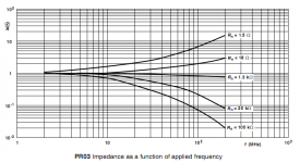
I just came across this plot and thought I'd share it here since it's something I haven't seen too often in datasheets...
The part in question is a 3W 5% 750V 250ppm metal film resistor. The datasheet (http://www.vishay.com/docs/28729/28729.pdf) is featuring an impedance plot where one can see that the part acts purely resistive up to 2MHz. I bet Magura would like these ;-)
The part in question is a 3W 5% 750V 250ppm metal film resistor. The datasheet (http://www.vishay.com/docs/28729/28729.pdf) is featuring an impedance plot where one can see that the part acts purely resistive up to 2MHz. I bet Magura would like these ;-)
Attachments
- Status
- Not open for further replies.
- Home
- Amplifiers
- Pass Labs
- What kind of resistor do you use?