🤦♂️
Unfortunately, or perhaps fortunately, I am unable to determine what this diminutive 'smilie' represents!

The OP's crossover is a simple 1st order series x-o with zobel on the woofer and parallel resistance on the tweeter with level adjustment.
Thank you for the description.
AllenB implied earlier that a simple series crossover can be higher order on the tweeter, depending on the components.
And that is what is necessary for this particular tweeter.
I shall therefore refer @Ron1200 back to post #28, to which AllenB gave a thumbs up.
This is what I think you are describing (with some help from MS Paint) 🙂I agree, but Ron does not presently have the measuring and simulator facilities required to produce an optimal design.
While the experts are evolving the original circuit, I'm conscious of the fact that the tweeter specs recommend a 2nd order crossover at 3,500 Hz.
Since Ron has already purchased 0.45 mH inductors, I offer him the following crossover circuit that will get him up and going until such times as he acquires the necessary crossover design facilities - should he wish to go down that route.
View attachment 1409814
C2 = 4.7 uF, L2 = 0.45 mH and L1 = 0.45 mH.
Between L2 and the tweeter I would add the attenuating resistors that I described in post #25 (R series = 1.8 ohm & R parallel = 15 ohm).
I am aware that the response is likely to be far from optimal, but at least the tweeter will be safe from low frequency overload.
C2 = 4.7 uF, L2 = 0.45 mH, L1 = 0.45 mH, R1 = 3 ohm, R2 = 15 ohm.
It is true that I don't have tools nor the expertise to design/redesign a crossover network. I also have limited time available to delve into this very interesting topic. I recently had a friend share an observation that I have too many projects and need to concentrate on a few less. Good advice I think.
As it stands now I have the original box and tweeter. The PE woofers has replaced the destroyed and NLA ADC woofers. The PE drivers were chosen based solely on their 8 ohm rating and ability to work in a .2cf sealed box. I know now that there is much more to selecting drivers.
So I was thinking... The original speaker designer must have done an ok job because the speakers did sound good. Since I don't possess the tools to do a redesign, maybe Its best just to replicate the original, knowing the original crossover did work with the original tweeter (and noting most of the components are in the tweeter circuit).
Everyone here has been very helpful in identifying the components. The only part left for me to identify is the variable resistor. I compared the two that I have the only number they have in common is 137 which is underlined. Can someone please direct me to a suitable replacement? The ones I've searched for are all over the place in their resistance values.
This is what I think you are describing...
That's it Ron, well drawn.
Just one amendment: R1 = 1.8 ohm.
Remember the above circuit is merely a seat of the pants suggestion and may require some tweaking. You could even try it without the bass inductor.
You could reconstruct the original series crossover as I indicated in post #28. However, that would give no solid guarantee since your mid/bass driver is not the original unit for which the series crossover was designed.
You pays your money and you takes your choice I'm afraid!
P.S I'm now considering your follow up post. I thought you wanted to dispense with the variable treble control?
The only part left for me to identify is the variable resistor.
You need a multimeter to measure the specs of the control. Do you own one?
Does the control have a third terminal? I only see two in your photograph.
Thanks Galu. I'll note the R1 value correction.Just one amendment: R1 = 1.8 ohm.
Remember the above circuit is merely a seat of the pants suggestion and may require some tweaking. You could even try it without the bass inductor.
You could reconstruct the original series crossover as I indicated in post #28. However, that would give no solid guarantee since your mid/bass driver is not the original unit for which the series crossover was designed.
You pays your money and you takes your choice I'm afraid!
P.S I'm now considering your follow up post. I thought you wanted to dispense with the variable treble control?
You are correct, I did want to simplify the crossover by deleting the treble control.
I have reconsidered this in light of the many variations possible and the tweaking that will be needed to fine tune the design given I don't have the tools or knowledge necessary to do a real design. I underlined the word "tweaking" as I am familiar the subsequent 'rabbit hole' I know I will be going down. And add in the associated delays ordering and trying different parts.
So to sum up my thinking: The original tweeter, with the original crossover design (accepting the limitations of the non-original mid/bass driver) is the most expedient way to get these reassembled and off my bench 🙂
Yes it has 3 terminals... I'll get some measurements from the other speaker. The one pictured is the one that melted.You need a multimeter to measure the specs of the control. Do you own one?
Does the control have a third terminal? I only see two in your photograph.
The original tweeter, with the original crossover design (accepting the limitations of the non-original mid/bass driver) is the most expedient way to get these reassembled and off my bench.
Fair enough, but remember that the original series crossover is not set up to match your replacement woofer. Hence, tweaking would be involved here too.
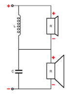
The original crossover is a series crossover (as so ably described by AllenB) and not a parallel crossover like the one I have previously illustrated.
Attached is the basic configuration of a 1st order series crossover (the tweeter is at the top):
Each crossover component is in series with one driver and in parallel with the other, requiring the characteristics of both drivers to be taken into consideration.
Attachments
Measurements
I sorry to report that I was unable to get any useful info from the variable resistor.
I tested (200 scale) between the center lug and one of the outer lugs while turning the knob. I would expect gradually increasing resistance as I moved the sweep away from the lug I was clipped to. This did not happen . Readings jumped around from a low of 15 to a high of 125 independent of the knobs position. i.e. as being turned it would read 25, 97, 15, 115, 36, 84... etc.
I then tested (200 scale) between the two outer lugs. This gave a steady reading of 40.
Hey Galu I just wanted thank you for all the hand holding you've provided me... Thanks Bud.
And to all the other form members that have chimed in, thanks you too. I'm so grateful and want to note how respectful you guys have been to me. A newbie with many dumb questions. Much appreciated!!!
Yes, good point. But given all the other options, seems like the mid/bass circuit might be the easier one to work on. Additional, I want to share that I have had these speakers working for many years as soundbar replacements for the TV. I didn't notice any issues, that is until they literally fell apart. 🙂Fair enough, but remember that the original series crossover is not set up to match your replacement woofer. Hence, tweaking would be involved here too.
I sorry to report that I was unable to get any useful info from the variable resistor.
I tested (200 scale) between the center lug and one of the outer lugs while turning the knob. I would expect gradually increasing resistance as I moved the sweep away from the lug I was clipped to. This did not happen . Readings jumped around from a low of 15 to a high of 125 independent of the knobs position. i.e. as being turned it would read 25, 97, 15, 115, 36, 84... etc.
I then tested (200 scale) between the two outer lugs. This gave a steady reading of 40.
Hey Galu I just wanted thank you for all the hand holding you've provided me... Thanks Bud.
And to all the other form members that have chimed in, thanks you too. I'm so grateful and want to note how respectful you guys have been to me. A newbie with many dumb questions. Much appreciated!!!

Thanks for your thanks!
It would appear that a standard 50 ohm wirewound control pot is what you need.

50 ohm 5 W pots like the above are available at Mouser in the UK (Mouser Part No 774-026TB32R500B1A1): https://www.mouser.co.uk/c/passive-...sistance=50 Ohms&termination style=Solder Lug
50 ohm 5 W pots are also available on UK ebay for around £6, as are superior 25 W ones for around £13.
It would appear that a standard 50 ohm wirewound control pot is what you need.
50 ohm 5 W pots like the above are available at Mouser in the UK (Mouser Part No 774-026TB32R500B1A1): https://www.mouser.co.uk/c/passive-...sistance=50 Ohms&termination style=Solder Lug
50 ohm 5 W pots are also available on UK ebay for around £6, as are superior 25 W ones for around £13.
I'm compelled to add:
In order to ensure long term reliability, I recommend a higher power rating than 5 W.
In order to ensure long term reliability, I recommend a higher power rating than 5 W.
Thanks but I already ordered the 5w pot. I ordered both 25 ohm and 50 ohm components. I reason I also selected the 25 ohm item is it has a Knurled Slotted Shaft like the original. I need this for the knob to fit into a recessed hole. I did look at the higher wattage pots but they are too wide and will not fit in the original cabinet location.
As a FYI... I measured the end-to-end resistance of the pot that was in the second speaker and it measured 2.4 ohms. The first speaker measured at 40 ohms.
The only thing I'm waiting to order is the 3.0 ohm resistors. The 'audio grade' ones I want are on back order.
As a FYI... I measured the end-to-end resistance of the pot that was in the second speaker and it measured 2.4 ohms. The first speaker measured at 40 ohms.
The only thing I'm waiting to order is the 3.0 ohm resistors. The 'audio grade' ones I want are on back order.
I'm not sure what's going on with the measurements there. Did the two pots have identical markings?
On considering the circuit, I suspect that a 25 ohm pot may actually be the better choice.
I await news of the outcome.
On considering the circuit, I suspect that a 25 ohm pot may actually be the better choice.
I await news of the outcome.
The pots had different markings. Additionally, each speaker's crossover resistors were different (brown round vs white sand cast), and one speaker had soldered connections with the other's connections being crimped. Note that the resistors were burnt and any identification marks were not readable on the brown ones. They resembled Mills, but I don't know for sure.Did the two pots have identical markings?
I will post up the final assembly once I have all the components.
Finally assembled the crossover. Replaced all with upgraded components. I'll install the new crossover in the speakers and report results in my MS-650 restoration thread once I've had a chance to listen to them. Thanks for the help.
Red + Black = Input
Red + Orange = Woofer
Blue + Black = Tweeter Pot
Blue + Orange = Tweeter

Red + Black = Input
Red + Orange = Woofer
Blue + Black = Tweeter Pot
Blue + Orange = Tweeter
- Home
- Loudspeakers
- Multi-Way
- What Kind of Crossover Am I Dealing With (Hybrid?)