I am far from an expert when it comes to crossovers. My previous experience has been limited to using capacitors to keep tweeters from frying. Geez, I just learned that this is called a simple First Order crossover.
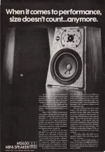
I am rebuilding a set of ADC MS-650 speakers from the late '70s. Originally my plan was just to replace the old parts with new and call it a day. Trouble is, both of my crossovers got so hot that I'm unable to read the markings on some of them. And additionally, the two crossovers look very different. They used different type of resistors (brown round vs white square) and different connections (soldered vs crimped). Also it appears to me that this might be some kind of First-Order (woofer) and Multi-Order (tweeter) hybrid crossover. But what do I know 🙂
Currently the replacement woofer is a GW-6PC-8 from PE (46 to 3,000Hz, 87.2dB). Though I have not found any info on the tweeter, I'm guessing that its a SEAS based on the number H217, the made in Norway label and look of the mounting plate.
As I never used the Lpad, I wouldn't mind simplifying the design and would welcome any suggestions. I plan on using higher quality parts.
Please excuse my low tech crossover drawing. I drew the woofer circuit and tweeter circuit separately to make it easier for me.
(Notes: The small resistor (5 Watt?) just before the Lpad measures 5.3 ohms on one speaker and 5.6 on the other. I cand find any info on the Lpad)

Speaker 1 crossover:

Speaker 2 crossover:

Melted Lpad:

Thanks
Ron
I am rebuilding a set of ADC MS-650 speakers from the late '70s. Originally my plan was just to replace the old parts with new and call it a day. Trouble is, both of my crossovers got so hot that I'm unable to read the markings on some of them. And additionally, the two crossovers look very different. They used different type of resistors (brown round vs white square) and different connections (soldered vs crimped). Also it appears to me that this might be some kind of First-Order (woofer) and Multi-Order (tweeter) hybrid crossover. But what do I know 🙂
Currently the replacement woofer is a GW-6PC-8 from PE (46 to 3,000Hz, 87.2dB). Though I have not found any info on the tweeter, I'm guessing that its a SEAS based on the number H217, the made in Norway label and look of the mounting plate.
As I never used the Lpad, I wouldn't mind simplifying the design and would welcome any suggestions. I plan on using higher quality parts.
Please excuse my low tech crossover drawing. I drew the woofer circuit and tweeter circuit separately to make it easier for me.
(Notes: The small resistor (5 Watt?) just before the Lpad measures 5.3 ohms on one speaker and 5.6 on the other. I cand find any info on the Lpad)
Speaker 1 crossover:
Speaker 2 crossover:
Melted Lpad:
Thanks
Ron
Hi Ron! I doubt if your crossover schematic is correct. The physical parts layout is hard to follow, so I think it may be best to simplify it.
For a simple 1st order crossover at 2,750 Hz, retain the 0.45 mH in series with the 8 ohm woofer and put a 10 uF film capacitor in series with the tweeter (assuming it to have a nominal impedance of 6 ohm).
If the tweeter is too loud, try putting the 3 ohm resistor in front of the capacitor (amplifier side) - add more resistance if you need more attenuation.
P.S. Your photos of the level control appear to show only two connecting tags, which would mean it was used as a variable resistor rather than an L pad.
Last edited:
P.P.S. I've just seen the other threads you have open on this speaker.
I'll give a link to both those threads here (I do note you linked to the first one up above).
It may be better if all discussions relevant to this speaker refurb are restricted to this one thread.
I'll give a link to both those threads here (I do note you linked to the first one up above).
With so little info available on these, I thought that I would document the restoration of the ADC MS-650 foam cabinet speakers.
I'm the original owner and have had these since ~1979-80. I purchased these from the ADC rep when working in the Jafco Stereo dept. They were selling these at a discount to people in sales to get the word out.

I'm the original owner and have had these since ~1979-80. I purchased these from the ADC rep when working in the Jafco Stereo dept. They were selling these at a discount to people in sales to get the word out.
What Type of Capacitor is This? Can/should this be replaced with a film cap in the speaker crossover? I'm unable to find anything that looks like it on google.
AC
TSI-8044
PXB25LR50
25uF-50VA* (* last character is obscured, assumed to be 'C')
The cap looks like this with the above markings (pic borrowed from a diyAudio post from 2011).

As used in my crossover:

AC
TSI-8044
PXB25LR50
25uF-50VA* (* last character is obscured, assumed to be 'C')
The cap looks like this with the above markings (pic borrowed from a diyAudio post from 2011).
As used in my crossover:
It may be better if all discussions relevant to this speaker refurb are restricted to this one thread.
Last edited:
Here's the simplified crossover circuit. The attenuating resistor(s) would be placed to the left of, and in series with, the capacitor.

If nothing else, it's a good starting point for experimentation.
If nothing else, it's a good starting point for experimentation.
Thanks Galu. Will do.It may be better if all discussions relevant to this speaker refurb are restricted to this one thread.

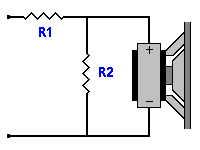
It looks likely that the high wattage 3 ohm and low wattage 5.6 ohm resistors were wired as a fixed L pad attenuator as shown in the attachment.
R1 = 3 ohm; R2 = 5.6 ohm
This fixed L pad arrangement would be placed after the capacitor and in front of the tweeter and would give about 6 dB of attenuation with the 6 ohm tweeter.
The variable resistor control was probably wired in such a way as to fine tune the attenuation, but we can simply take it out of the equation.
Attachments
That was my first impression as well. In cases like this it helps to consider whether it is a series crossover.I doubt if your crossover schematic is correct.
What do you think of this?
Glad that you published that, it's similar ( no wonder...!) to the one that I made lately, minus the first res on the (-)path , which is useful for attenuate the tw (in addition to the shunting one). Any hint of what values to hit for the RC cell ?
I have 1.5 mH-1,5 uF-8Ω2 by now, 9 cm midbass and mica tweeter with horn, both 16 Ω
I have 1.5 mH-1,5 uF-8Ω2 by now, 9 cm midbass and mica tweeter with horn, both 16 Ω
The 1" tweeter with ferrofliid, H217, certainly is Seas and look like a customer specific version of H253 or H254. Trimmed faceplate for one.
Manufactured werk33 in 1980 if interpret the kabel correct.
Are they working well and have you considered replacing the ferrofluid?
Finnaly, do you know what midbass was originally installed?
Manufactured werk33 in 1980 if interpret the kabel correct.
Are they working well and have you considered replacing the ferrofluid?
Finnaly, do you know what midbass was originally installed?
A simple series crossover does do first order and higher. This depends on the Q of those two components. While it's typically not more than 9dB/oct, it can be much higher.
What do you think of this?
It certainly does explain why there are two capacitors coming off the positive terminal in Ron's sketch!😎
Whereas I was simply suggesting a workable parallel version - unfortunately with only 6 dB electrical slope on both drivers.
If you were to identify the value of each of the components in your diagram, I'm sure that would be most helpful to Ron in reconstructing the crossover using new components where necessary.
A simple series crossover does do first order and higher.
I suppose a potential fly in the crossover ointment is that the woofer currently being used will have different characteristics to the original?
I have redraw the XO in a more convential diagram.
1st order with some shaping and attentuation on the tweeter. The red connection is likely in error.

dave
1st order with some shaping and attentuation on the tweeter. The red connection is likely in error.
dave
The way forward depends on Ron's equipment, experience and willingness to be accurate. Yes, we could obtain values and impedance data and reverse engineer the old crossover.If you were to identify the value of each of the components in your diagram,
On the other hand we could just make comparisons to the old and new woofer. The easiest way would be to simply fit the woofer and try to adjust the tweeter with knowledge of the potentiometer.
The third option is to begin from scratch. There would be no harm in moving to a regular (not series) crossover if that's considered simpler.
I have redraw the XO in a more convential diagram.
Your version certainly looks faithful to Ron's sketch, Dave, and highlights his mistaken connection.
@Ron1200 I think you will be able to follow Dave's schematic with ease. If you wish to simplify the design as you stated in post #1, then the level control and the 5.6 ohm resistor in line with it can be removed. The tweeter negative terminal would then be wired directly to the negative input terminal.
The tweeter will then run unattenuated. If it proves to be too loud it can be attenuated in the fashion illustrated in post #6.
P.S. I suspect that this information is sufficient and that you won't want to go down the path of designing a new crossover from scratch.
Ron's, Dave's and mine are identical if I'm not mistaken. Do you see an error?Your version certainly looks faithful to Ron's sketch, Dave, and highlights his mistaken connection.
- Home
- Loudspeakers
- Multi-Way
- What Kind of Crossover Am I Dealing With (Hybrid?)