When I get to the reply screen, your schematic disappears, so I made notes. Hopefully, I'll catch at least the high spots.
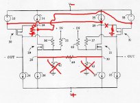
Actually, the link between points 38 and 39 is still there. It's the connection between the Sources of the front end differential.
R40 does not exist.
R42 and 43...well they do and they don't exist. Depending on how you want to look at things, you could say that they're gone...or that they've been replaced by R1/R4 and R44/R45 in the original Aleph-X schematic.
The criss-cross thing you drew is heading in the right direction, conceptually. The thing you have to keep in mind is that "X" feedback is going to be a question of phase. The Aleph-X front end drive crosses over to the other side in order to keep the feedback negative. (Positive feedback is bad ju-ju, of course.) I think the patent shows the output stages as being followers, which don't invert phase, whereas the Aleph output does. If you wanted to design a follower output, then the drive and the feedback would remain on the same side of the circuit. If you're using an output that inverts, you'll need to cross either the drive or the feedback to the other side. Topologically, it's the same thing either way--it was just easier to draw the schematic the way I did; I was born lazy and had a relapse.
Grey
ok so the main thing is that:
the feedback has to be negative, and "feedback borns negative", so on a follower amplifier, where phase isn't changed, you simpli have to keep the feedback line on the same side
but, on an aleph, the output it at opposite phase, so if you keep the feedback on the same line, it becomes positive, so you have to "cross"
am I right?
now I have to understand why nelson's shematic is a follower, i thought it was a phase changing amplifier
I played a little with spice, and Nelson's shematic inverts the phase!
so, there's a problem somewhere...
so, there's a problem somewhere...
If when you say "Nelson's schematic," you are
referring to the circuit shown on the cover page of
patent #5,376,899, you have two folded cascodes
coupled together by their non-inverting inputs.
The input at the Gate of MOSFET 20 will be
inverted when it gets to the Drain of 20. It then
feeds the Source of MOSFET 30. This being
connected as a common-gate, you don't get
another phase inversion.
So overall, it is an inverting amplifier.
The mirror image is another inverting amplifier,
ideally being driven by a the negative-phase of the
incoming signal. The common-mode bits are
subtracted away by differential nature of the
circuit.
The feedback of each side makes each half
more like the other, you might say, perfecting the
subtraction.
Erik
Bricolo said:ok so the main thing is that:
the feedback has to be negative, and "feedback borns negative", so on a follower amplifier, where phase isn't changed, you simpli have to keep the feedback line on the same side
but, on an aleph, the output it at opposite phase, so if you keep the feedback on the same line, it becomes positive, so you have to "cross"
am I right?
I believe so.
You only want one phase inversion per side in
order to feed a signal with opposite phase back to
Gate of the diff pair MOSFET.
You can get this by grabbing the output of the
diff-pair that matches your phase: the one from
the opposite MOSFET.
Erik
Oops...right...the outputs aren't followers. I knew I'd get something cranked backwards once I lost the schematic...sorry about that.
Grey
Grey
Ok, si if nelson's shematic is the correct one (of course it is 😀)
why is grey's so different? Especially if it uses the same concept (2 gain stages, the first being the diff pairs)
why is grey's so different? Especially if it uses the same concept (2 gain stages, the first being the diff pairs)
It's different on account of the fact that I like breaking rules. Life is more fun when you think outside the box. Egad, I'd die of boredom if I had to build standard three stage, cookie cutter amps as per Self & Slone. (If you feel that you must read one, read Self. Slone is intolerable.) One or two are okay, but a steady diet of that kind of thing kills your spirit.
I view the world as a set of building blocks. Like a kid, I play with the blocks, putting them together in one order, then another, seeing what will happen. Nothing to it. It's just play. I enjoy it. When something goes right, I learn. When something goes wrong, I learn. As long as I'm learning, I'm happy. (Though I reserve the right to cuss if I blow something up along the way.)
Grey
For whatever reason, the Aleph circuit looked more interesting to me than the "X" circuit, so I set the X aside and played with the Alephs for a while. Then it occurred to me that the two building blocks could be combined, so I got out the X patent and stared at it for a while.
It took a bit before I got it. The problem was that I was counting gain stages and current sources and followers and whatnot. I couldn't see the forest for the trees. Too many details. I had to stand back and look at it from a greater distance.
Note that patents are made to be unreadable. It's part of their function. They are not textbooks, nor are they meant to be. That's not to say that you can't learn from them if you're patient.
X is just a strategy for negative feedback in a balanced circuit. Add the communication via the bridge between the Sources/Emitters/Cathodes and you're done. That's all. Nothing more and nothing less. Until you release the details and look at the picture as a whole it will remain mysterious and you will be frustrated.
The schematic on the patent shows what I think of as "same side" feedback. The only "breakthrough" I managed was to realize that the signal could cross from one side to the other and still fulfill the intent of the circuit. Whether you use "same side" or "opposite side" feedback depends on whether you've chosen inverting building blocks or non-inverting building blocks to play with.
Nelson was already there, of course. It's his circuit and he's had plenty of time to play with it and try it out in different ways. Chances are he's got variations I haven't thought of.
You're looking for something more complicated than it really is. Like those pictures composed of spots, sometimes you just have to look at it a while before the pattern emerges.
Some people raise eyebrows because Nelson used the 'non-inverting input' of the transistor, i.e. the Source. Take a moment and think about how a differential works. Assuming that you're using it with a single-ended input, the back side of the differential receives its signal via the Source (assuming MOSFETs). Maybe thinking of the Source as an input will help.
The circuit almost treats discrete gain devices as opamps, with both inverting and non-inverting inputs (albeit with different gain characteristics). Using two inputs into a discrete device isn't perhaps what most people would call normal, but there's no reason that it shouldn't work. It's just that--with the exception of a differential--you don't see it very often in audio circuits.
Grey
If you want to see the Aleph-X conceptually
look more like the "same-side" feedback topology
as in the patent, you can redraw it as a
Source-follower driving a common-Gate stage,
the drain of which drives the gate of the Aleph
current-sourced output stage. Then you feed the
output back to the gate of your Source-follower.
Then you'd mirror that.
Grey recognized that there's no reason why the
differential pair couldn't just do all the work of
coupling the halves, and offering up the proper
phase to the output at the same time.
No muss, no fuss, no extra MOSFETs required.
The more I read about it and think it over, the
more I want to build one of these things. 🙂
Erik
- Status
- Not open for further replies.
- Home
- Amplifiers
- Pass Labs
- What is X in the Aleph-X?