Hello,
i have removed 2 suspicious resistors from an amplifier and PSU board. One is open, one is tested at 3.8M with my DMM. So almost open i think.
The problem is the colors of the bands, they are not easy to read. I see 2 golden bands, 2 white bands, and maybe a purple (passed) one, what do you see?
They are each one connected from the output of a full wave rectifier(+ and - 50VDC), and to the center lug of a voltage regulator (supposed to give + and -15 VDC) and also to the center lug of an unknown transistor. That's all i have.
Many thanks helping me to decrypt these resistors...
They are probably fuses or fuse resistors. Before attempting to change them, you should elucidate what happened downstream and cause them to blow, and remedy that problem
Looks to me like it’s supposed to be blue gray gold gold, followed by a white band. That would make a 6.8 ohm “fuse”. You do need to determine why it blew, and of course whether my assumption about being 6.8 ohms is right. It’s a logical standard value, any other way of reading/interpreting doesn’t make as much sense. The color rendering in the pic isn’t very good.

The service schematic/model/brand and part location would greatly help in determining where/if a problem exists.
Without that information, this thread will go on with speculations endlessly.
Without that information, this thread will go on with speculations endlessly.
Yes, it makes sense. I saw this value on a similar schematic. I post the drawing i made from the pcb ASAP.Looks to me like it’s supposed to be blue gray gold gold, followed by a white band. That would make a 6.8 ohm “fuse”. You do need to determine why it blew, and of course whether my assumption about being 6.8 ohms is right. It’s a logical standard value, any other way of reading/interpreting doesn’t make as much sense. The color rendering in the pic isn’t very good.
Many thanks
Here is what i think there is on the PCB. I don't know yet the zener diode.
The transistor is OK. Unless the regulator is bad, i don't see what has caused the blown resistor.
There is the same for the +15V connected to the +50V.
I can't read nothing on the regulator.
Is my schematic has sense? I don't get why the transistor... To lower the input voltage for the regulator?
The transistor is OK. Unless the regulator is bad, i don't see what has caused the blown resistor.
There is the same for the +15V connected to the +50V.
I can't read nothing on the regulator.
Is my schematic has sense? I don't get why the transistor... To lower the input voltage for the regulator?
Attachments
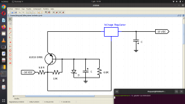
Regulators have input voltage maximum ratings.
Usually around the 30 volt area.
So the transistor has to drop some unwanted voltage in order to feed the regulator, and not over-stress it.
The zener controls the amount of reduction.
The center connection of the 15v regulator should be tied to ground though.
You have it going to B+?
Is there a brand name, a schematic available of this no-name amp?
It's the analogic board of a Technics SX PX336 Digital piano. It feeds the digi board and has a stereo amplifier on it.
I'm gonna check again for the reg's center tap to ground. Maybe there is a diode before ...
The center tap is like this. And there is a zener to ground at the output
I'm gonna check again for the reg's center tap to ground. Maybe there is a diode before ...
The center tap is like this. And there is a zener to ground at the output
Last edited:

The output zener is likely used to limit or protect downstream voltage surges should the regulator fail.New schematic : the zener seems to be conductive, 1500 ohm to the ground. On the other side the diode is in one way only...
But why a zener on the output?
It's probably an 18 volt zener which would not interfere with the regulator in normal use, but clamp voltage at 18V if the regulator ever shorted out or loses regulation.
Again, a complete schematic or the service manual would tell me more, because even though I'm a 45+ year service tech, I dislike having to speculate on a partial snippet of a schematic.
Zeners usually fail dead short, or open. Failing as 1.5Kohm when tested at low voltage with a multimeter would be unusual I would think - you are measuring with one leg of the zener desoldered, right?
It's unusual for a zener that does not conduct under normal conditions therefore remains cold, such as the second one in your circuit following the voltage regulator IC, to be the primary failure.
It is however very common for higher voltage zeners that are used as shunt regulators to fail as they run very hot under normal conditions. Eventually they die due to heat cycling. The first zener in your circuit is doing exactly this task and I would suspect it to be a likely source of failure. It's probably a 22-33V zener or something in that ballpark. The transistor acts as a pre-regulator, outputting the zener voltage minus 0.6V which is within the acceptable range of the regulator IC and also means the regulator IC doesn't need to drop as much voltage so runs cooler (as a tradeoff, the transistor runs hotter). It also acts as a 'capacitor multiplier' - the capacitor in parallel with the first zener can be a lot smaller than if a capacitor was put directly on the input terminals to the regulator IC to try to reduce voltage ripples.
If the first zener fails open circuit this could cause a cascade failure of almost the entire circuit - the voltage at the regulator IC input goes to high, it fails short circuit causing the output to go too high, output zener conducts heavily and possibly fails short circuit, transistor possibly fails due heavy current, fuse blows.
I would test both zeners, the transistor and the regulator IC. If you don't have the tools to check them thoroughly then I'd just replace all 4 components because if you leave any blown components in the circuit you will blow up the new components that you did replace. To check a zener you need to remove it and check the reverse voltage is correct by connecting to a bench powersupply - a simple forward diode test on a multimeter may not be enough to catch one that is partially failed. Also check there isn't another source of a short circuit on the -15V supply.
Last edited:
Maybe the -15VDC is IN and the -50VDC is OUT? and the output is -5.0VDC to feed some digital circuit and the "6.8R" is an inductor?It feeds the digi board and has a stereo amplifier on it.
Outside of the circuit, the output zener diode are healthy. I checked the 2 power transistors inside the circuit with my DMM, and they seem OK also.
So i don't see what has blown the fuse resistors. Except that i still read a 740 ohm resistance from output to ground on -15 v output which i don't have on the other side.
So i don't see what has blown the fuse resistors. Except that i still read a 740 ohm resistance from output to ground on -15 v output which i don't have on the other side.
For the negative side, i think it's normal for a DMM to find 1500 ohm to ground because of the zener and the transistors that's let pass the + from the DMM.
Maybe a keyboard or the digi board is shorting some where...
Maybe a keyboard or the digi board is shorting some where...
- Home
- Design & Build
- Parts
- What is this resistor