Here's the background: I am starting a multi-pronged attack on my satellite receiver (Bell 3100) to get better quality audio out of it. The lack of bass has been driving me crazy and now it has turned to obsession. The digital part is under control and I have parts on order and know what I'm doing there. Now the analog:
The attached schematic is for each channel of analog output. That is as much as I could trace out before I got lost. My question is, is the circuit acting as a high pass filter in any way? Can I do away with any part of it?
The attached schematic is for each channel of analog output. That is as much as I could trace out before I got lost. My question is, is the circuit acting as a high pass filter in any way? Can I do away with any part of it?
Attachments
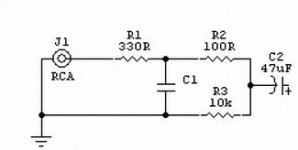
NO matter how bad is the bass of your receiver it is certainly not because of filtering. Your circuit is mostly a low pass filter but the 47uF will have some effect on low frequencies. Not enough circuit for anything useful. Stop being lazy 🙂
analog_sa said:Stop being lazy 🙂
I can assure you that this is the opposite of being lazy. I am trying to add optical & coax digital outputs PLUS muck around with the analog output. The problem is that since this is new territory I can never know how much bass is actually in the source signal so until I try a bunch of things I can never know if something will work.
I am baffled by the polarized cap. I suspect that the audio signal entry point is the junction of R2 R3 C2, but could it actually be serially through C2? What other use would C2 likely have?
I found this:
http://www.diyaudio.com/forums/showthread.php?postid=546623#post546623
Very similar output stage. I guess it must be some ubiquitous commercial design. I'll have to keep searching for a quick-and-dirty improvement to it.
http://www.diyaudio.com/forums/showthread.php?postid=546623#post546623
Very similar output stage. I guess it must be some ubiquitous commercial design. I'll have to keep searching for a quick-and-dirty improvement to it.
Information overload.....so many designs out there....
So if I do manage to trace out more of the circuit including the op amp driving the output, any recommendation for an easy improvement?
So if I do manage to trace out more of the circuit including the op amp driving the output, any recommendation for an easy improvement?
Adding an optical output to the 3100 should not be too difficult. The sound will be clearer, less noise, and should have more bass (will still be stereo though).
Parts needed:
425-1100-5-ND X 1 = (TRANSMITTER FIBER OPTIC 8MBPS)
311-100ACT-ND X 1 = (RES 100 OHM 1/8W 5% 0805 SMD)
311-1141-1-ND X 2 = (CAP .10UF 25V CERAMIC X7R 0805)
Optical jack location
Solder locations picture
Instructions:
- remove solder from 3 spots shown
- solder on three smaller components 2 capacitors and one resistor
- solder in Toslink transmitter
- last drill hole and reassemble
(source: wlo from Maestra forums)
Dont know about the coax though.. you could always use a convertor box if it was really necessary.
btw let me know if you figure out any ways to improve either the analog sound out or the picture quality.. My receiver has some crappy picture quality problem. Most likely due to the lack of cooling and chips overheating.
Thanks. I know all that. Actually, your information is a bit out of date. The GP1FA511TZ is obsolete and Sharp's current replacement is the GP1FA514TZ.
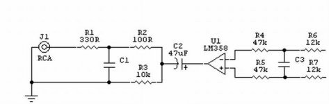
1. Change that LM358 for something better (almost anything is better than that ).
).
2. Change R2 for 50R.
3. Remove C1.
4. Remove R1 and put a wire link.
5. Enjoy.😎
Btw, the lack of bass must be the LM358 and/or something behind it, like an ultra-cheap dac.
).2. Change R2 for 50R.
3. Remove C1.
4. Remove R1 and put a wire link.
5. Enjoy.😎
Btw, the lack of bass must be the LM358 and/or something behind it, like an ultra-cheap dac.
Thanks for all your help. Just to close out the thread, I thought I would post what I finally did.
I tried bypassing all the output circuitry, in other words, op amp output through a single PP cap straight out. Difference was negligible.
I then added the Toslink output. I did wind up mucking around with the circuit a bit, but I am not completely sure if it was a connection mistake or the current FO TX requires different supporting components. I used 330R resistors and both 0.1 uF and 18 pF caps and it works regardless. As I mentioned above, the part to buy is Sharp GP1FA514TZ.
The bass is great! It is so amazing to not have my sub plate amp go into sleep mode when I watch TV! 🙂
As for coax output, I was satisfied with performance from the FO, so I just switched my DVD to coax from FO cabling so that I could connect everything into the smallish number of inputs in my receiver.
Sharp GP1FA514TZ - where to buy?
I'm looking to buy a few Sharp GP1FA514TZ FO transmitters. anyone know who sells these?
Thanks
I'm looking to buy a few Sharp GP1FA514TZ FO transmitters. anyone know who sells these?
Thanks
Dolby 5.1 or not?
I'm having a "discussion" with a friend about the modifying a 3100 for the optical output. Here is the question:
Will the 3100 output Dolby 5.1 (AC3) when there is program material encoded in 5.1? If not, what format would be output? Dolby 2.0? ProLogic?
Thanks
I'm having a "discussion" with a friend about the modifying a 3100 for the optical output. Here is the question:
Will the 3100 output Dolby 5.1 (AC3) when there is program material encoded in 5.1? If not, what format would be output? Dolby 2.0? ProLogic?
Thanks
Re: Dolby 5.1 or not?
No, no, and no, in that order. 🙂 It is just a 2 channel stereo PCM output.
ndc_11 said:Will the 3100 output Dolby 5.1 (AC3) when there is program material encoded in 5.1? If not, what format would be output? Dolby 2.0? ProLogic?
No, no, and no, in that order. 🙂 It is just a 2 channel stereo PCM output.
- Status
- Not open for further replies.
- Home
- Source & Line
- Digital Source
- What is this circuit element?